
A simple project with AT90S2313

The schematic for this project involves a simple circuit where the ATmega microcontroller controls an LED using PWM. The ATmega8 or its successors can be used as the central processing unit, connected to the LED through PB1. The circuit design should incorporate a bypass capacitor (C4) to stabilize the power supply to the microcontroller, ensuring reliable operation. Resistor R2 serves to limit the current flowing through the LED, which is critical for preventing damage to both the LED and the microcontroller's output pin. The PWM signal generated by the microcontroller will determine the brightness of the LED, creating a visual effect as it ramps on and off every two seconds.
The software component of the project is encapsulated in the demo.c file, which contains the necessary code to configure the timer and handle the PWM output. The use of the iocompat.h file allows for compatibility across various AVR devices by abstracting the differences in register names and configurations. This modular approach simplifies the code and enhances its portability. The interrupt service routine (ISR) is crucial for managing the timing of the PWM signal, allowing the microcontroller to enter a low-power sleep mode between interrupts, thereby optimizing power consumption.
In summary, this project serves as an excellent introduction to using GNU tools for AVR programming, demonstrating the integration of hardware and software to achieve a practical application of pulse-width modulation with an LED display.You should have the GNU tools configured, built, and installed on your system. In this chapter, we present a simple example of using the GNU tools in an AVR project. After reading this chapter, you should have a better feel as to how the tools are used and how a Makefile can be configured. This project will use the pulse-width modul ator (PWM) to ramp an LED on and off every two seconds. An AT90S2313 processor will be used as the controller. The circuit for this demonstration is shown in the schematic diagram. If you have a development kit, you should be able to use it, rather than build the circuit, for this project. Meanwhile, the AT90S2313 became obsolete. Either use its successor, the (pin-compatible) ATtiny2313 for the project, or perhaps the ATmega8 or one of its successors (ATmega48/88/168) which have become quite popular since the original demo project had been established.
For all these more modern devices, it is no longer necessary to use an external crystal for clocking as they ship with the internal 1 MHz oscillator enabled, so C1, C2, and Q1 can be omitted. Normally, for this experiment, the external circuitry on /RESET (R1, C3) can be omitted as well, leaving only the AVR, the LED, the bypass capacitor C4, and perhaps R2.
For the ATmega8/48/88/168, use PB1 (pin 15 at the DIP-28 package) to connect the LED to. Additionally, this demo has been ported to many different other AVRs. The location of the respective OC pin varies between different AVRs, and it is mandated by the AVR hardware. The source code is given in demo. c. For the sake of this example, create a file called demo. c containing this source code. Some of the more important parts of the code are: As the AVR microcontroller series has been developed during the past years, new features have been added over time.
Even though the basic concepts of the timer/counter1 are still the same as they used to be back in early 2001 when this simple demo was written initially, the names of registers and bits have been changed slightly to reflect the new features. Also, the port and pin mapping of the output compare match 1A (or 1 for older devices) pin which is used to control the LED varies between different AVRs.
The file iocompat. h tries to abstract between all this differences using some preprocessor #ifdef statements, so the actual program itself can operate on a common set of symbolic names. The macros defined by that file are: TIMER1_CLOCKSOURCE the clock bits to set in the respective control register to start the PWM timer; usually the timer runs at full CPU clock for 10-bit PWMs, while it runs on a prescaled clock for 8-bit PWMs ISR() is a macro that marks the function as an interrupt routine.
In this case, the function will get called when timer 1 overflows. Setting up interrupts is explained in greater detail in
For modern parts (at least for the ATmega 128), however Atmel has drastically increased the IO source capability, so when operating at 5 V Vcc, R2 is needed. Its value should be about 150 Ohms. When operating the circuit at 3 V, it can still be omitted though. /* * - * "THE BEER-WARE LICENSE" (Revision 42): *
Related Circuits
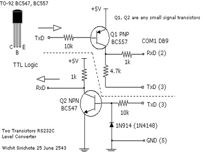
When connecting a microcontroller project to a COM port on a PC, an RS-232 converter is required. Various chips can accomplish this task, such as the MAX232 and DS275. However, for a simple and cost-effective RS-232 converter, the following...
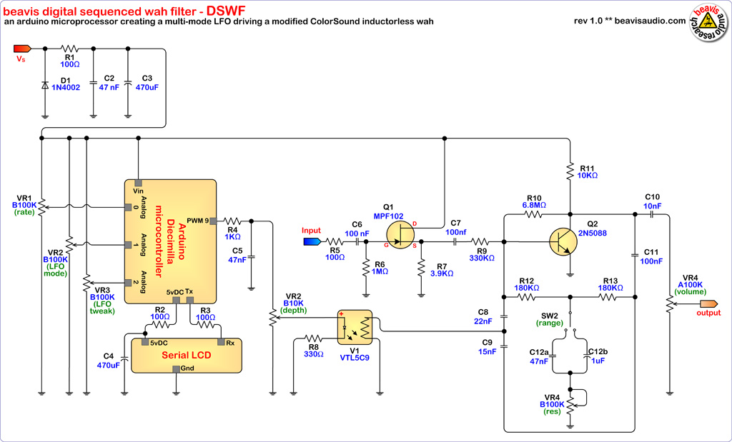
The microcontroller (MCU) is responsible for sending variable voltages over time, similar to a traditional Low-Frequency Oscillator (LFO), to an effect that can be modulated by voltage or a potentiometer on a conventional analog effect that can be replaced...
This AM receiver is working perfectly without the need of coils or even a variable capacitor. The LF356 is the basic component. P1 and P2 are the frequency selectors. Use a small telescopic antenna. The stations selectivity is not...
Communication with the MCP3028 ADC chip is achieved through a straightforward serial interface that adheres to the SPI protocol. The PIC16F84 or PIC16F628 does not possess a hardware SPI peripheral. However, a software-implemented SPI protocol can facilitate communication with...
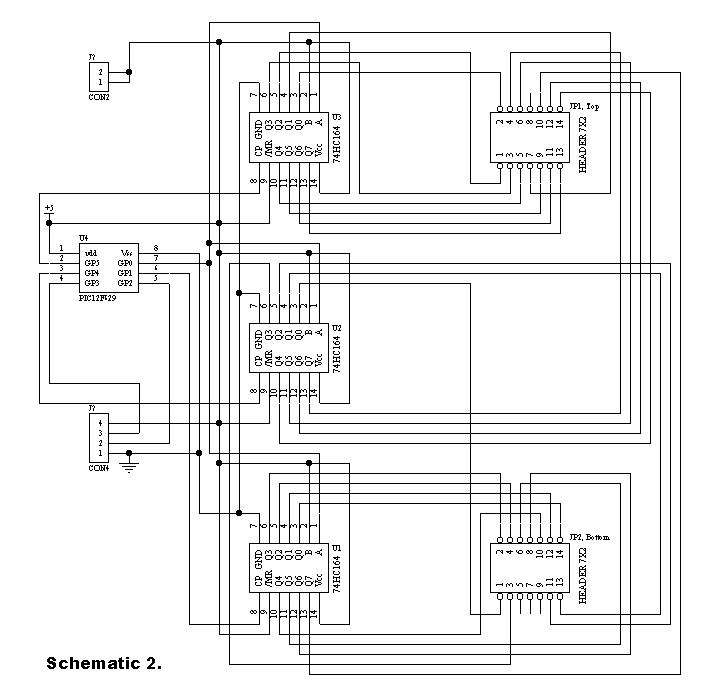
This project meets a specific need by utilizing a frequency counter built with basic TTL chips, predating the availability of CMOS HC versions. The design incorporates four chips: three HC TTLs and an Atmel AT90S2313 microcontroller. It features a...
A board is to be designed with a single input of 120 volts and 600 watts, which will provide more than three outputs, each rated at 120 volts and 200 watts. These outputs will be designated as A, B,...