
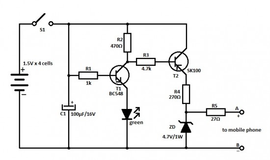
a single transistor smart battery charger

The smart battery charger circuit described operates primarily through a single transistor that acts as a switch to control the charging process. When the battery voltage drops below a defined threshold, the transistor is activated, allowing current to flow from the power source to the battery, thus initiating the charging cycle. The design's simplicity, which avoids the complexity of integrated circuits, can be advantageous for educational purposes or low-cost applications.
However, the sensitivity to temperature is a critical drawback. The circuit's performance can vary significantly with temperature changes, leading to inaccurate charging behavior. This sensitivity can result in either undercharging or overcharging the battery, potentially shortening its lifespan or causing damage. The mentioned sensitivity of 0.5V per 10°C highlights the need for careful temperature management or compensation techniques in practical applications.
For portable devices, integrating the circuit into an external charger can help alleviate some of these issues, as it allows for better thermal management and isolation from temperature fluctuations. This method can ensure a more stable charging environment, improving reliability. However, in applications such as UPS systems or homemade backup power supplies, the reliance on a single transistor circuit may limit performance. In these cases, more robust designs that incorporate temperature compensation or utilize multiple components may be necessary to ensure reliable operation across varying environmental conditions.
Overall, while the single transistor battery charger circuit presents an interesting and simplified approach to battery management, its limitations must be carefully considered in the context of the intended application.Electronic Design has a smart battery charger schematic using only a single transistor. This is interesting as similar circuits now contain simple integrated circuits. When the battery`s charge falls below a threshold voltage, it is automatically recharged to a preset voltage. Unfortunately, the circuit has a couple of major flaws. The single sili
con junction makes the circuit extremely sensitive to ambient temperature changes. In the comments, someone mentions 0. 5V per 10 ° which sounds about right. For portable devices, you can avoid the second flaw by building the circuit into an external charger. However, this is not possible with UPS`s or other homemade backup power supplies.
🔗 External referenceRelated Circuits
This is an ideal mobile charger that utilizes 1.5-volt pen cells to charge mobile phones while traveling. It can replenish a cell phone battery three or four times. The mobile charger circuit is designed to be compact and portable, making...

The battery should charge up to 14 volts. A reading of 10.7 volts indicates that one cell is shorted. A good way to diagnose this further is to look at the water level in the cells. The shorted cell...

A common need in many systems is to obtain positive and negative supplies from a single battery. Where current requirements are small, the circuit shown is a simple solution. It provides symmetrical +&- output voltages, both equal to one...
This design integrates power-on and low-battery indication features, capable of operating with any battery voltage up to 15V. It exhibits a very low current drain of 2mA or less. The circuit design incorporates a power-on indicator that activates when the...
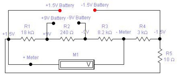
The circuit diagram of a DC battery tester designed by Matthew B. This circuit can measure DC batteries ranging from 1.5V to 9V. Component Parts List: R1 = 18K Ohm, R2 = 240 Ohm, R3 = 8.2K Ohm, R4...
The RH1078M is a micropower dual operational amplifier in a standard 8-pin configuration. This device is optimized for single supply operation at 5V, with specifications also available for ±15V. Linear Technology provides numerous demo boards at no cost to...
Warning: include(partials/cookie-banner.php): Failed to open stream: Permission denied in /var/www/html/nextgr/view-circuit.php on line 713
Warning: include(): Failed opening 'partials/cookie-banner.php' for inclusion (include_path='.:/usr/share/php') in /var/www/html/nextgr/view-circuit.php on line 713