
1.5v to 9v battery tester

The DC battery tester circuit designed by Matthew B is a practical tool for measuring the voltage of batteries within the range of 1.5V to 9V. The circuit consists of several resistors (R1, R2, R3, R4, R5) that create a voltage divider, allowing the panel meter (M1) to provide an accurate reading of the battery voltage. The values of the resistors are chosen to ensure that the panel meter operates within its optimal range while providing sufficient sensitivity to detect small voltage changes.
The LAN tester circuit, created by Vassilis Stergiopoulos, offers versatility with two design options. The first design employs the IC555 timer and the 4017 decade counter, which together allow for the detection of network connectivity through LED indicators. The second design utilizes the ATtiny2313 microcontroller, providing a more compact and programmable solution for LAN testing.
The low-resistance connection tester is an essential tool for verifying the integrity of electrical connections. It operates by measuring resistance values between 0.25 and 4 ohms, making it suitable for testing cables, soldered joints, and other connections. The use of a 741 op-amp in differential mode enhances the circuit's ability to detect minute voltage differences, ensuring reliable continuity testing.
The remote control tester circuit is designed for simplicity and cost-effectiveness. By employing the TSOP1738 infrared receiver module, it can easily detect signals from infrared remote controls. The circuit's design allows for a straightforward construction process, making it accessible to hobbyists and professionals alike.
The 12V NiCAD battery charger circuit is engineered to charge batteries efficiently. It begins charging at a rate of 75 mA and transitions to a trickle charge once the battery is fully charged. This method ensures that the battery can be fully recharged within approximately four hours, while the current and voltage limiting features of the circuit extend the battery's lifespan. The visual indicators, such as lamp L1 and the LED, provide clear feedback on the charging status, enhancing user experience and safety.Here the circuit diagram of DC battery tester designed by Matthew B. This circuit can be used to measure DC battery from 1. 5V up to 9V. Component Parts List: R1 = 18K Ohm R2 = 240 Ohm R3 = 8. 2K Ohm R4 = 3K Ohm R5 = 10 Ohm M1 = Panel Meter (Anyone will. This LAN tester circuit originally designed by Vassilis Stergiopoulos. This LAN tester circuit optionally has two designs. The first design is built based 2 main ICs that are timer IC555 and decade counter 4017. The second design is based microcontroller chip ATtiny2313 (the other kind of microcontroller should be work). The first design circuit (555. Here the low resistance connection tester which can be used as cable or wire tester, soldered joints and other types of connection with resistance value between 0.
25 and 4 ohm. Notes This simple circuit uses a 741 op-amp in differential mode as a continuity tester. The voltage difference between the non-inverting and inverting inputs is. Here is the remote control tester circuit. This circuit is really a simple and easy tester for verifying the basic operations of an infrared remote control unit. It is low-cost and very easy to construct. The tester is designed around infrared receiver module TSOP1738. Operation of the remote control is identified by a tone from. The following diagram is the schematic diagram of 12V NiCAD battery charger with charging rate of 200mA/Hour.
This NiCAD battery charger circuit charges the battery at 75 mA until the battery is charged, then it reduces the current to a trickle rate. It will fully recharge a dead/unpowered battery in 4 hours and the battery. The following diagram is the schematic diagram of Ni-CAD Battery Charger circuit which featured with current and voltage limiting to keep the battery lifetime.
The lamp L1 will be light brightly and the LED will be out when the battery is low and battery charging in progress, but the LED is very bright and the. 🔗 External reference
Related Circuits
This is a transistor tester integrated into a circuit or printed circuit board (PCB). It is utilized when a project does not function correctly, allowing for the testing of electronic components. The transistor tester is a crucial tool in electronic...
Camping today often requires bringing various electronic devices for daily use or entertainment. Typically, a charged lead-acid battery and a power inverter are utilized to ensure a well-organized holiday where family members can enjoy their electronic gadgets. It is...
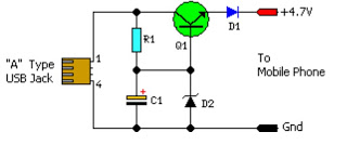
This simple circuit provides a regulated output of 4.7 volts for charging mobile phones. A USB outlet delivers 5 volts DC at a current of 100 mA, which is adequate for slow charging of mobile devices. Most mobile phone...
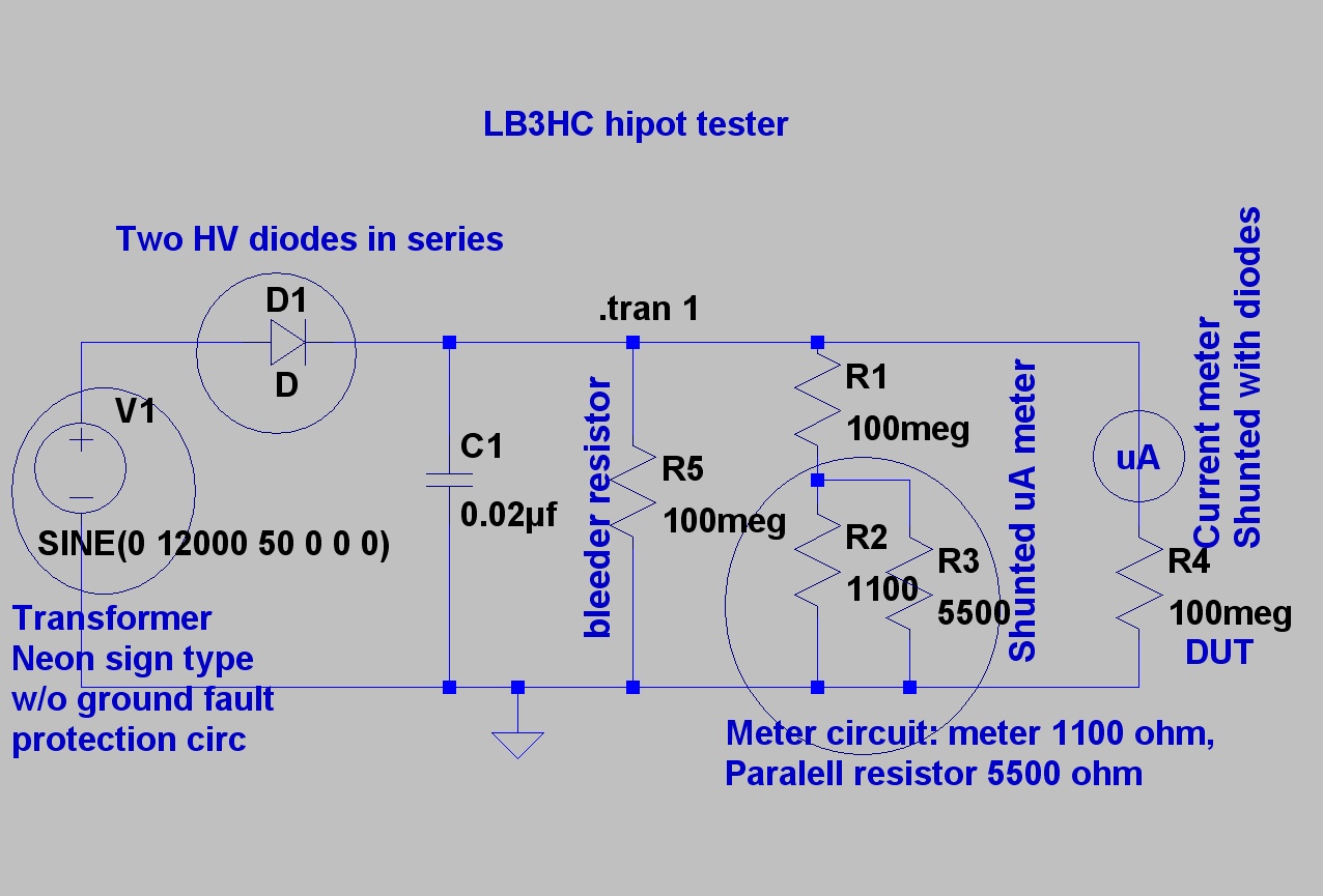
The design is based on concepts from K8CU and AG6K, but the circuit has been simplified and uses different components. The mechanical encapsulation has also been modified. LTspice was utilized to verify the tester prior to construction. The schematic...
The article describes the process of building a charger controller board and programming the AVR microcontroller. A Li-Ion battery is needed for practice; the example battery mentioned has withstood considerable abuse. Knowledge of the battery's specifications, such as maximum...
Most 24V power systems in trucks, 4WDs, RVs, boats, and similar applications utilize two series-connected 12V lead-acid batteries. The charging system is capable of maintaining the total voltage of the individual batteries. If one battery is experiencing failure, this...