
A Smart Barn Door Drive for Astrophotography

A tracking mount for astrophotography, particularly for cameras like the Minolta SRT-101, is essential for capturing celestial events without the blurring effects caused by Earth's rotation. The barn door mount is a practical and economical solution for amateur astrophotographers, allowing for longer exposures by compensating for the Earth's movement. The design's simplicity, utilizing basic materials and mechanical principles, makes it accessible for users with limited resources.
The fundamental operation of the barn door mount relies on a hinge mechanism that allows two boards to open in an isosceles triangle formation. The drive screw, when turned, adjusts the angle of the boards to maintain alignment with the celestial objects being photographed. This setup requires precise calibration to ensure that the hinge axis is aligned with the north celestial pole, which is critical for effective tracking.
In more advanced configurations, the use of a microcontroller can automate the drive screw's motion, allowing it to adjust the speed dynamically based on the exposure time. This adaptation minimizes tracking errors and enhances the quality of the images captured. The integration of stepper motors and CMOS logic circuits enables precise control over the drive mechanism, facilitating a smoother operation than manual adjustments.
Overall, the barn door mount exemplifies a blend of mechanical ingenuity and electrical engineering, providing a versatile tool for capturing the beauty of the night sky. By addressing the challenges posed by Earth's rotation and optimizing the tracking mechanism, this design significantly enhances the potential for successful astrophotography.A tracking mount for trusty Minolta SRT-101. My untracked photos of Hyakutake had not done the comet justice; the exposures were too short. If one mounts a camera to a sturdy tripod and opens the shutter for several minutes, the developed picture will be trailed, with every object in the frame creating a short or long streak depending on the length of the exposure and the part of the sky being imaged. Because of the Earth`s motion, the positions of the stars shift during any long exposure, thereby limiting the practical exposure time for a fixed camera. This limit works out to around 30 seconds for a normal wide-angle lens. Of course, very long exposures exploiting this effect have their own artistic appeal, but To counteract the Earth`s rotation and allow longer exposures, some kind of drive system is needed.
If an equatorially-driven telescope is available, it can provide the tracking with the camera mounted piggy-back on the side. For beginning astrophotographers seeking a more economical approach, a barn door mount is a simple way to track a camera for wide-angle pictures.
The simplest barn-door drive consists of two pieces of wood, hinged at one end. One piece is mounted to the tripod and has a threaded rod going up through the end opposite the hinge. This drive screw is turned by hand at regular intervals, or driven by a motor, to gradually push the boards apart.
If the hinge axis is aligned with the north celestial pole, very near the star Polaris, a camera riding on the top board will have the Earth`s motion canceled out, resulting in sharp images of the sky. This basic configuration is sometimes called a tangent arm drive, because the drive screw and the boards form a right triangle.
If the screw is turned at a constant rate, errors accumulate rapidly. A popular variation is the isosceles or single-arm drive. Here the screw screw is pivoted at both ends, forming an isosceles triangle as the boards open. In published designs, the screw is almost always driven at a constant rate using a stepper motor and an oscillator/divider circuit built from standard CMOS logic. Some simple math shows how the angular velocity of the mount is related to the motion of the drive screw: In other words, the angular velocity of the mount, omega, will not be constant when the drive screw is turned at a constant rate yielding constant (dL/dt).
The approximation to perfect tracking is much better than the tangent-arm drive, but significant errors will accumulate after a few minutes. To further reduce tracking errors, a mechanical scheme involving multiple boards and hinges has been used[1].
If the dimensions are chosen correctly, the sine approximation errors in this system will mostly cancel out. While interesting, this is not appealing to an electrical engineer. Anything mechanical is hard, or at least harder than circuits and software, so why not take the easy way out and vary the speed of the drive screw, counteracting the errors in the single-arm drive This may be accomplished with a single-chip design (a microcontroller), making the electrical construction no more difficult than the classic circuits designed around SAA-xxxx chips.
and the boards are opening at the hinge at a constant angular rate ” just what we need. Notice that (dL/dt = 2axcos(at)), indicating that perfect tracking is achieved when the drive rate slows down over time. Mechanically, the smart barn door uses a single-arm (isosceles) design, as this is easy to build and can track longer before running out of screw length.
For 🔗 External reference
Related Circuits
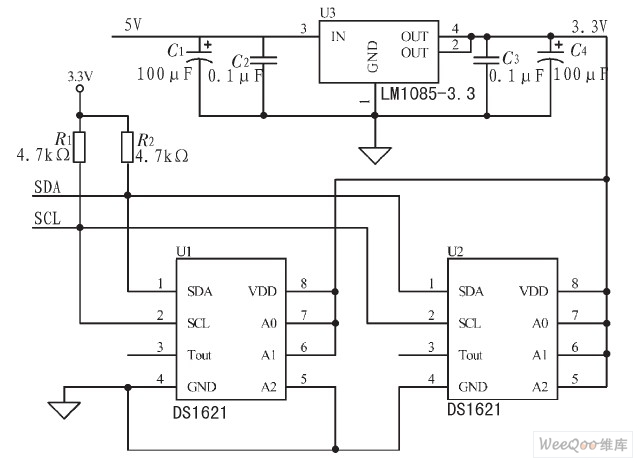
The IIC bus line is a type of communication protocol that facilitates the transmission of data between devices. It is characterized by its simplicity in construction and wiring, making it suitable for various high-performance applications. The operating system, particularly...

This circuit schematic produces a beep and/or illuminates an LED when someone touches the door handle from outside. The alarm will continue to sound until the circuit is switched off. The circuit operates on the principle of capacitive sensing, where...
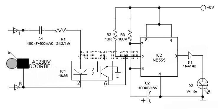
This 6V battery-operated doorbell light circuit can be connected in parallel with any existing AC 230V doorbell. When the doorbell switch is pressed, the bell sounds as usual, and the AC mains supply available across the doorbell is routed...

The M-88L70 is a complete DTMF receiver that combines both band-split filter and decoder functions into a single 18-pin DIP or SOIC package. It is manufactured using CMOS process technology, which allows for low power consumption (maximum 18 mW),...
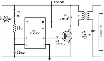
Whenever there is a need for battery-powered lighting, such as for camping, solar-powered cottages, cars, boats, planes, or emergency situations, fluorescent lamps are highly appealing. They are significantly more efficient than incandescent lamps, producing much more light for less...
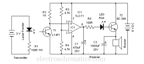
This laser door alarm operates by detecting the interruption of a laser beam. A low-cost laser pointer serves as the light source. When an individual crosses the path of the laser beam, it triggers the alarm. The laser door alarm...