
12vdc fluorescent lamp driver schematic

The described circuit provides an efficient solution for driving a 12 V fluorescent lamp, particularly in applications where battery power is essential. The utilization of a standard transformer in reverse allows for a straightforward approach to achieve high voltage from a low voltage source. The TLC 555 timer IC, known for its versatility, is configured in an astable mode, which enables it to produce a continuous square wave output. This output serves as the control signal for the MOSFET, which functions as a switch to modulate the current flowing through the primary winding of the transformer.
The choice of a MOSFET for amplification is critical, as it can handle higher frequencies and provides greater efficiency compared to bipolar junction transistors. The output from the MOSFET is coupled to the primary of the step-up transformer, which transforms the lower voltage input into a much higher AC voltage suitable for driving the fluorescent lamp. The design eliminates the need for a filament warm-up period, allowing for immediate illumination upon activation.
In practical applications, this circuit can be integrated into portable lighting systems, emergency lights, or off-grid solar-powered setups. The efficiency of fluorescent lamps combined with this driver circuit makes it an ideal choice for energy-conscious users seeking reliable lighting solutions in various environments. Proper consideration should be given to component ratings to ensure reliability and safety during operation, particularly in applications involving high voltage output.Whenever there is a need for battery-powered lighting, like for camping, solar powered cottages, cars, boats, planes, or emergency purposes, fluorescent lamps have a great appeal. Firstly, they are very much more efficient than glow lamps, so they produce much more light for less power consumption.
Secondly, their light color stays constant while the battery runs down. In this article I will offer driver circuit for 12 V/5Watt fluorescent lamp, this circuit used a normal 220 to 10V stepdown transformer in reverse to step 12V to about 240V to drive a lamp without the need to warm the filaments. The IC1 TLC 555 is wired as an astable multivibrator for producing the necessary oscillations. The MOSFET Q1 is used to amplify the oscillations produced by the IC1. The out put of MOSFET is connected to the primary of the step up transformer to produce a ~240 V AC for driving the florescent lamp.
🔗 External reference
Related Circuits

A thirty mining lamp control ASIC production delay lamp circuit is straightforward. It utilizes the HL2102 IC from Wuxi Love Core Microelectronics Co., Ltd. The circuit is designed to control a light with a timed delay, allowing for regular...
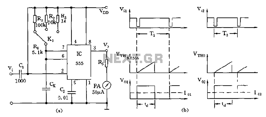
The circuit utilizes a 555 timer along with timing resistors R1 to R3 and a measured capacitance Cx to create a capacitance meter. The principle of capacitance measurement in a one-shot circuit is based on the relationship between the...

A DC brush motor driver circuit diagram utilizing the MC33035 chip is presented, illustrating a typical configuration for driving a straight DC brush motor. The circuit incorporates a field-effect transistor (FET) bridge driver setup. When transistor VT3 is activated,...

This circuit can be used to drive a 12V relay with a triggering signal of 5V. It incorporates two 1N4002 diodes, one 2N3904 transistor, and two resistors. By altering the resistor values, the input triggering voltage can be modified. The...
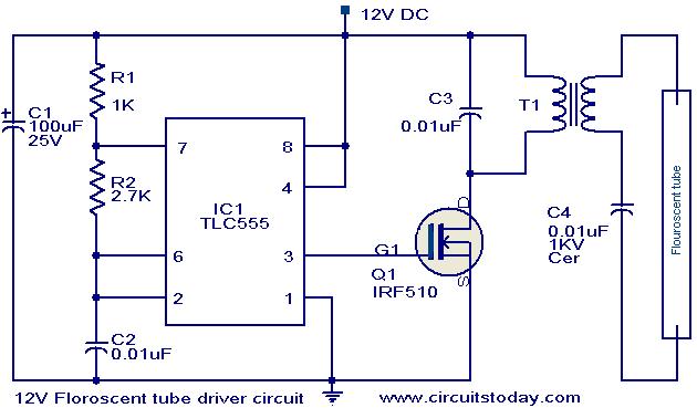
This circuit provides a simple and effective method for driving fluorescent lamps using a 12 V power supply. The circuit consists of an oscillator, a MOSFET switch, and a step-up transformer to power the fluorescent lamp. The TLC 555...
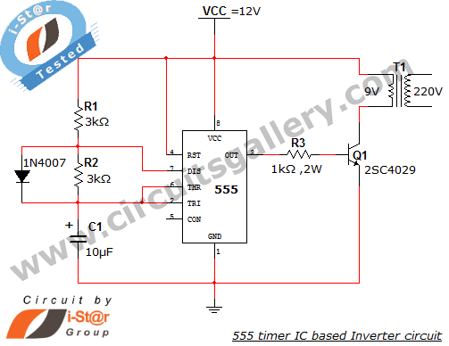
This article explains what an inverter is and how to construct a simple, low-cost 12V to 220V inverter circuit. An inverter functions as a DC to AC converter and is a valuable electronic product for compensating for emergency power...