
A transformerless Tesla coil
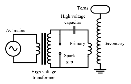
The circuit described operates by utilizing a transformerless design that leverages multiple resonance frequencies to enhance energy transfer efficiency. The arrangement of capacitors, inductors, and the spark gap plays a crucial role in the performance of the system. The choice of components, such as the specific values of inductance and capacitance, is critical in achieving the desired resonance conditions. The use of a neon sign transformer as a power supply is appropriate for generating the high voltages required for operation while maintaining manageable current levels. The flexible wiring and mechanical connections allow for easy modifications and adjustments during experimentation. The grounding method employed provides a necessary safety feature while maintaining circuit functionality. Overall, this circuit exemplifies innovative approaches to Tesla coil design, focusing on efficiency and simplicity without compromising performance.Continuing the studies about directly coupled multiple resonance networks operated as Tesla coil like devices, I built a 6th-order system, that is equivalent to a " Tesla magnifier ", but without a transformer. The schematic diagram is shown below: This circuit has several potential advantages over a simpler directly coupled Tesla coil : Faster en
ergy transfer from C1 to the distributed terminal capacitance C3, what results in smaller losses, greater efficiency, and insensitivity to tuning precision. The wider notches in the primary waveforms tend to cause fast quenching of the spark gap, at the first notch, trapping all the energy in the high-voltage part of the circuit.
The design is restricted by the absence of the extra degree of freedom allowed by a transformer in the classic magnifier circuit, with the maximum voltage gain being forced by the ratios among the resonance frequencies, but the transformerless construction is simpler. The system was designed to have three resonance frequencies, in the ratio 5:6:7. In this way it can transfer the energy in C1 to C3, ignoring losses, in just three cycles (in 12. 5 µs), instead of in the 11 cycles (in 37. 6 µs) required by the 4th-order directly coupled system with the same input (identical) and output (almost identical) capacitances.
The power supply is a 5000 V, 30 mA neon sign transformer with a single floating output, that charges the capacitor C1, that is then discharged through a multiple spark gap starting the energy transfer transient. C1 is a 5. 09 nF "MMC" capacitor, the same that I used with the 4th-order system. L3, the output resonator coil with 28. 2 mH, the terminal with a telescopic antenna, the NST and the spark gap are also the same. Their description can be seen here. The other two coils are L1, with 87 µH, made with 42 turns of insulated 1 mm2 wire over an 8. 8 cm PVC tube, and L2, with 1521 µH, made with 257 turns of #18 magnet wire, also over a PVC tube. C2 is a flat plate high-voltage capacitor, that produced the best tuning with the other elements with 257 pF.
No filters or special protection circuits were included, since the power is not high. The ground connection goes to just a metal bucket in the ground. The components are simply disposed over a table, interconnected with flexible wires with terminals at the ends, between brass screws and nuts mounted in the elements. Insulating supports are inserted below the floating elements. C2 was, in a first attempt, an adjustable capacitor made with a PVC tube having a fixed inner plate of aluminum foil and an adjustable outer plate.
Worked well at low power, but when in operation at full power the construction resulted in a lot of corona, and progressive capacitance change due to surface deterioration of the PVC, probably with metal deposition, that increased the capacitance and detuned the system. When I tried to improve the insulation by applying wax around the edges of the plates, it failed almost immediately with a puncture.
A new capacitor was then made with simply two flat plates glued to an acrylic plate, in contact with terminals fixed to the plates, with the dimensions calculated to result in 247 pF. But due to an error (I disconsidered the fringe field at the borders of a test capacitor made to determine the dielectric constant of the acrilic plate) it resulted smaller, with 211 pF.
I realized, however, that corona around the plates would increase the effective capacitance by approximately the correct amount. The capacitor worked well. I didn`t try to improve its insulation in the first tests (and the plates would have to be a little larger without the corona).
The obtained performance was somewhat better than with the 4th-order system, a fact evidenced by the presence of streamers coming not only from the terminal antenna, but also from the disk at the base of the terminal. It also produces a kind of corona haze around the terminal that 🔗 External reference
Related Circuits
This side will explain how to calculate toroid coils. I have made toroid tests with different number of turns and measured the inductance. Formula: L (nH) = N² * AL. Where: L = inductance in nanohenrys. N = number...
To create a full-scale Tesla Coil that produces at least 6 inches of sparks, also referred to as "artificial lightning." Current Status: The project was successful, with a complete full-scale, full power test conducted on Friday, July 15, 2011....
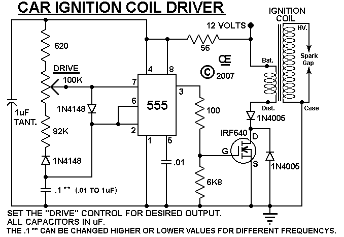
An ignition coil is being used to generate sparks, controlled by a MOSFET powered by a 555 timer. The MOSFET is confirmed to be switching. The circuit involves a 555 timer configured in astable mode to generate a pulse-width modulation...
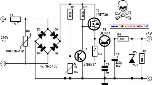
An increasing number of appliances draw a very small current from the power supply. When designing a mains-powered device, one typically chooses between a linear and a switch-mode power supply. However, for appliances with very low total power consumption,...
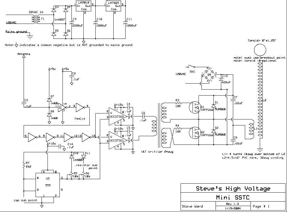
The design is a clone of Steve Ward's MiniSSTC circuit; the schematic is reprinted here with credits to Steve Ward. This circuit performs very well for a low power and simple SSTC. The design is based on Steve's final...
This circuit creates a buzz coil using a standard automotive ignition coil. A 556 dual timer is employed to establish the frequency and duty cycle of the coil current. One timer functions as an oscillator to generate the 200...