
How to calculate toroidcoils

Toroid coils, commonly used in inductors and transformers, can be accurately characterized by calculating their inductance. The inductance \( L \) in nanohenries (nH) is determined using the formula \( L = N^2 \times AL \). Here, \( N \) represents the number of turns wound around the toroidal core, while \( AL \) is the inductance factor specific to the core material and geometry, expressed in nanohenries per turn squared.
To perform these calculations, it is essential to first ascertain the inductance factor \( AL \) for the specific toroidal core material being used. This value can often be found in manufacturer datasheets or through empirical testing. The core's geometry, including its dimensions and material properties, significantly influences the \( AL \) value.
Once \( AL \) is known, the inductance can be calculated for various winding configurations. For example, if a toroid has an \( AL \) value of 100 nH and is wound with 10 turns, the inductance can be computed as follows:
\[
L = 10^2 \times 100 = 10000 \, nH \, (or \, 10 \, \mu H)
\]
This formula allows for the design and optimization of inductors in various applications, such as filters, oscillators, and power supplies. It is also crucial to consider the effects of core saturation and temperature variations on the inductance, which may require adjustments to the design for specific applications. Proper measurement techniques should be employed to verify the calculated inductance against actual performance in circuit conditions.This side will explain how to calculate toroidcoils. I have made toroid tests with different number of turns and measured the inductance. Formula : L (nH) = N2 *AL. Where: L = inductance in nanohenrys. n = number of turns. AL = inductance factor. 🔗 External reference
Related Circuits
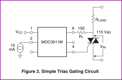
A small circuit is being constructed to control a 200W heater using a MOC3023 optoisolator and a BT136 triac. The datasheet for the optotriac suggests a specific circuit configuration. The inquiry pertains to the determination of the 180-ohm resistor...
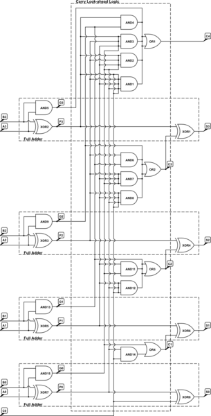
A 4-bit Carry Look Ahead Adder has 3 gate delays for all carry bits and 4 gate delays for all sum bits, whereas ripple adders have 7 and 8 gate delays, respectively. The 4-bit Carry Look Ahead Adder (CLA)...
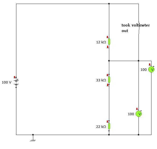
A user is utilizing YENKA software to diagram circuits but is experiencing confusion regarding the voltage calculations in a basic series circuit, as illustrated in the attached image. In a basic series circuit, components are connected end-to-end, forming a single...
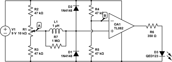
The circuit above is a canonical AC coupled common emitter amplifier, which is typically used as a linear amplifier rather than a switch that activates when the input exceeds a certain level. The AC coupled common emitter amplifier is...
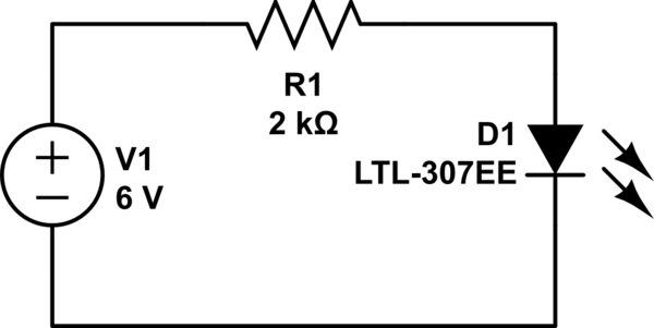
It cannot be 0 volts, as the current does not flow freely due to the presence of the resistor. This results in one side being more negatively charged and the other side more positively charged, as electrons can move...
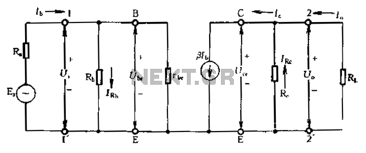
Calculate magnification, input resistance, and output resistance circuit. This circuit is designed to calculate the magnification, input resistance, and output resistance of a given electronic system. The magnification refers to the ratio of the output signal to the input signal,...