
A typical laptop power adapter circuit

The laptop power adapter circuit operates by first taking the incoming 22V AC voltage and converting it to a higher DC voltage of +30V using a rectifier bridge followed by a smoothing capacitor. The rectifier circuit typically consists of four diodes arranged in a bridge configuration, allowing for full-wave rectification. The smoothing capacitor filters out the ripples in the rectified voltage to ensure a steady DC output.
The UCC38050P integrated circuit serves as a pulse-width modulation (PWM) controller, providing efficient control of the switching element, usually a MOSFET. This PWM controller regulates the output voltage by adjusting the duty cycle of the switching signal, ensuring stable operation under varying load conditions.
The transformer (L1) is designed to step down the voltage from the primary side to the secondary side. The turns ratio of the transformer is critical, as it determines the output voltage level. The secondary winding of the transformer outputs a lower AC voltage, which is then rectified by another set of diodes to produce the final +12V DC output.
The entire circuit is typically equipped with additional components such as inductors and capacitors for filtering and stability purposes, ensuring that the output voltage is smooth and free from noise. Protection features may also be included, such as over-voltage and over-current protection, to safeguard both the adapter and the connected device. The design of the laptop power adapter circuit is crucial for providing reliable power to laptops while maintaining efficiency and safety standards.A typical laptop power adapter circuit A typical laptop power adapter circuit, the AC 22V voltage through the rectifier filter circuit output after +30V DC voltage, and then th e switch oscillation circuit Ul (UCC38050P), switch control, the transformer Li transformer secondary output rectifier + 12V DC voltage.
Related Circuits

The schematic for this tutorial is straightforward. It involves connecting the ADXL320 sensor to the PIC microcontroller and an LED. The power supply is assumed to be a +5V battery to power the PIC. A custom power circuit can...

This is a versatile digital counter circuit that is cost-effective due to the basic components available in many electronic shops. The digital counter circuit is designed to count pulses and display the count on a digital readout, typically using a...
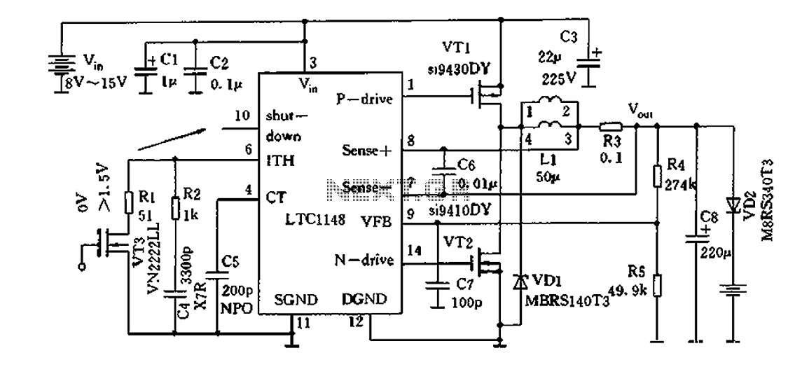
Efficient nickel-cadmium battery charger IC (LTC1148) circuit The LTC1148 is an integrated circuit designed for the efficient charging of nickel-cadmium (NiCd) batteries. This charger IC features a constant current/constant voltage (CC/CV) charging method, which is essential for optimizing the charging...
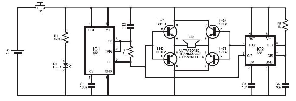
This ultrasonic sensor circuit consists of a set of ultrasonic receivers and transmitters that operate at the same frequency. When an object moves within the covered area, the circuit's balance is disturbed, triggering the alarm. The ultrasonic circuit is...
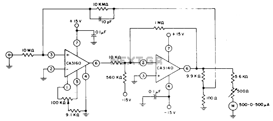
The circuit employs CA3160 and CA3140 BiMOS operational amplifiers to achieve a full-scale meter deflection of ±3 pA. The CA3140 functions as a 1T0 gain stage, supplying the necessary positive and negative output swing for the meter and the...
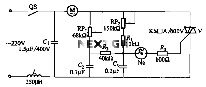
The 3P10 circuit, illustrated in the figure, utilizes a bidirectional thyristor for control. The adjustment potentiometer RPi allows for modification of the minimum motor speed, while the adjustment potentiometer RP2 enables continuous variation of the motor speed, reaching up...