
Ultrasonic Sensor Circuit

To solder components correctly, the following procedure is recommended: First, heat the soldering iron and place its tip on the component lead while holding the solder wire at the point where the lead exits the board. The iron tip should contact the lead just above the PCB. As the solder melts and flows, wait until it evenly covers the area around the hole and the flux boils out from beneath the solder. The entire process should not exceed five seconds. After removing the iron, allow the solder to cool naturally without blowing on it or moving the component. A properly executed joint will have a bright metallic finish, with smoothly ended edges on both the component lead and the board track. If the solder appears dull, cracked, or blob-like, it indicates a dry joint, necessitating the removal of the solder (using a solder pump or wick) and redoing the connection. When soldering sensitive components, it is advisable to hold the lead from the component side of the board with long-nose pliers to dissipate any heat that could damage the component. Avoid using excess solder to prevent short circuits between closely spaced tracks. After completing the work, trim the excess component leads and clean the board thoroughly with an appropriate solvent to eliminate any remaining flux residues.
Given the complexity of the circuit, careful attention is required to avoid mistakes that could be difficult to trace and repair later. It is recommended to solder the pins and IC sockets first, followed by the remaining components, such as resistors, trimmers, and capacitors, ensuring the correct orientation of electrolytic capacitors. Next, solder the transistors and diodes, taking care to prevent overheating. The transducers should be positioned to avoid direct interference with each other, as this can reduce circuit efficiency. After soldering, it is crucial to check all connections and ensure the circuit functions as intended.This Ultrasonic Sensor Circuit consists of a set of ultrasonic receiver and transmitter which operate at the same frequency. When something moves in the area covered the circuit`s fine balance is disturbed and the alarm is triggered.
The ultrasonic circuit is very sensitive and can be adjusted to reset itself automatically or to stay triggered til l it is reset manually after an alarm. The ultra sonic transmitter is built around two NAND gates wired as inverters and they form a multivibrator the output of which drives the transducer. The trimmer P2 adjusts the output frequency of the transmitter and for greater efficiency it should be made the same as the frequency of resonance of the transducers in use.
The ultrasonic receiver uses a transducer to receive the signals that are reflected back to it the output of which is amplified by the transistor TR3, and IC1 which is a 741 op-amp. The output of IC1 is taken to the non inverting input of IC2 the amplification factor of which is adjusted by means of P1.
The ultra sonic circuit is adjusted in such a way as to stay in balance as long the same as the output frequency of the transmitter. If there is some movement in the area covered by the ultrasonic emission the signal that is reflected back to the receiver becomes distorted and the circuit is thrown out of balance.
The circuit works from 9-12 VDC and can be used with batteries or a power supply. The board is made of a thin insulating material clad with a thin layer of conductive copper that is shaped in such a way as to form the necessary conductors between the various components of the circuit. The use of a properly designed printed circuit board is very desirable as it speeds construction up considerably and reduces the possibility of making errors.
In order to solder a component correctly you should do the following: Take the hot iron and place its tip on the component lead while holding the end of the solder wire at the point where the lead emerges from the board. The iron tip must touch the lead slightly above the p. c. board. When the solder starts to melt and flow wait till it covers evenly the area around the hole and the flux boils and gets out from underneath the solder.
The whole operation should not take more than 5 seconds. Remove the iron and allow the solder to cool naturally without blowing on it or moving the component. If everything was done properly the surface of the joint must have a bright metallic finish and its edges should be smoothly ended on the component lead and the board track.
If the solder looks dull, cracked, or has the shape of a blob then you have made a dry joint and you should remove the solder (with a pump, or a solder wick) and redo it. When you are soldering a sensitive component it is good practice to hold the lead from the component side of the board with a pair of long-nose pliers to divert any heat that could possibly damage the component.
Make sure that you do not use more solder than it is necessary as you are running the risk of short-circuiting adjacent tracks on the board, especially if they are very close together. When you finish your work cut off the excess of the component leads and clean the board thoroughly with a suitable solvent to remove all flux residues that may still remain on it.
There are quite a few components in the circuit and you should be careful to avoid mistakes that will be difficult to trace and repair afterwards. Solder first the pins and the IC sockets and then following if that is possible the parts list the resistors the trimmers and the capacitors paying particular attention to the correct orientation of the electrolytic.
Solder then the transistors and the diodes taking care not to overheat them during soldering. The transducers should be positioned in such a way as they do not affect each other directly because this will reduce the efficiency of the circuit. When you finish soldering, chec 🔗 External reference
Related Circuits
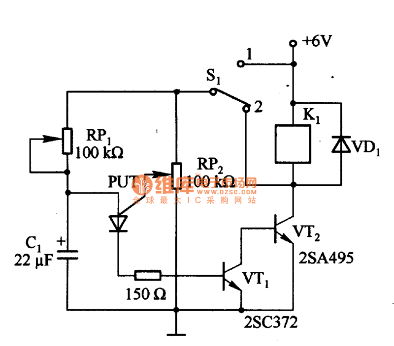
Figure 1 consists of a Programmable Unijunction Transistor (PUT) and an automatic interval timer circuit. In this circuit, the PUT serves as the oscillator. The switch S1 is used to toggle between interval timing and automatic timing modes. When...
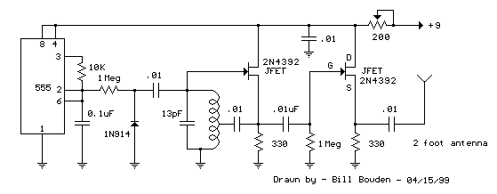
This circuit will transmit a continuous audio tone on the FM broadcast band (88-108 MHz) which could be used for remote control or security purposes. Circuit draws about 30 mA from a 6-9 volt battery and can be received...
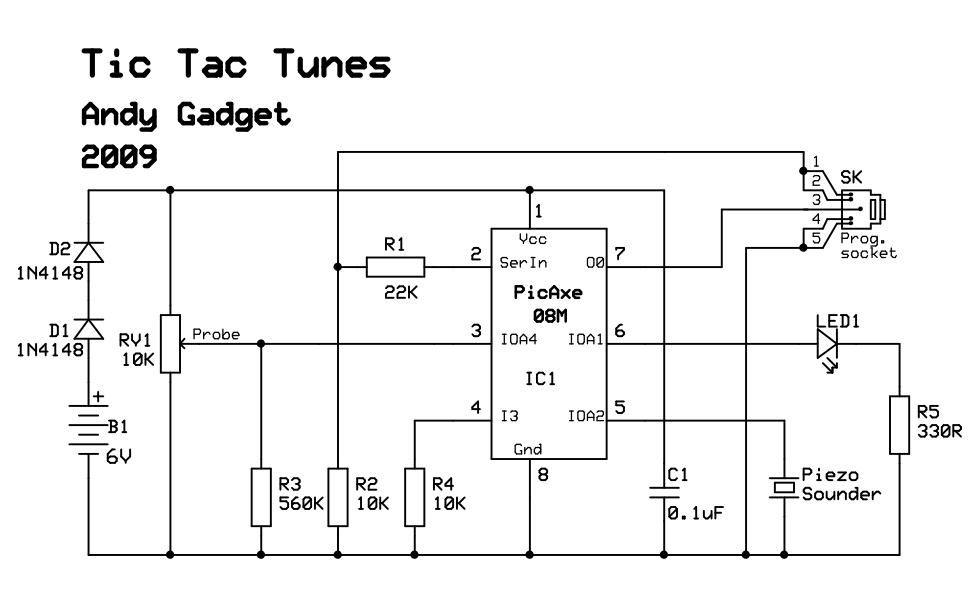
Due to limited space, a small 6V battery is utilized, and the voltage is reduced by 1.2V to 4.8V using diodes D1 and D2. The PicAxe chip is employed in the circuit. In this circuit design, the primary power source...
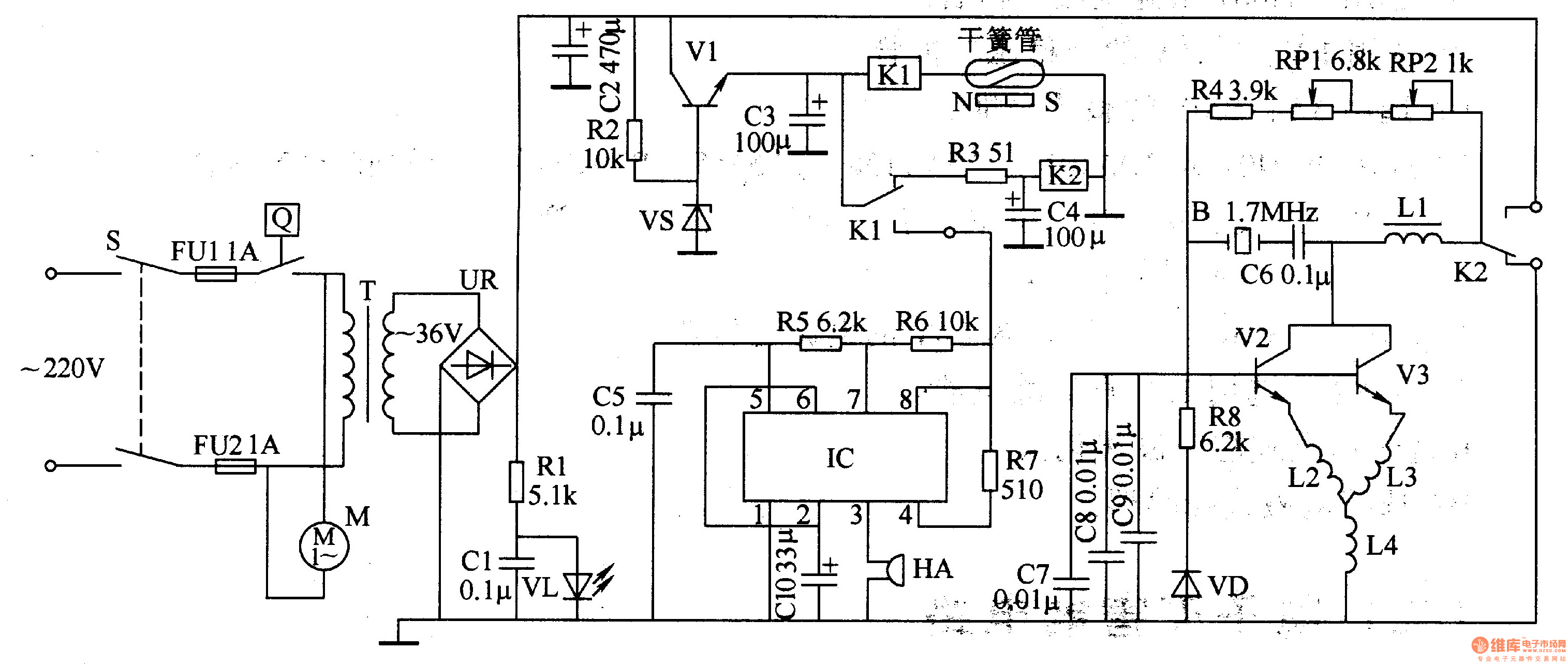
The ultrasonic atomizer circuit consists of a power supply circuit, control circuit, water detection alarm circuit, and an ultrasonic oscillator, as illustrated in Figure 3-190. The power supply circuit includes a power switch (S), fuses (FU1, FU2), a timer...
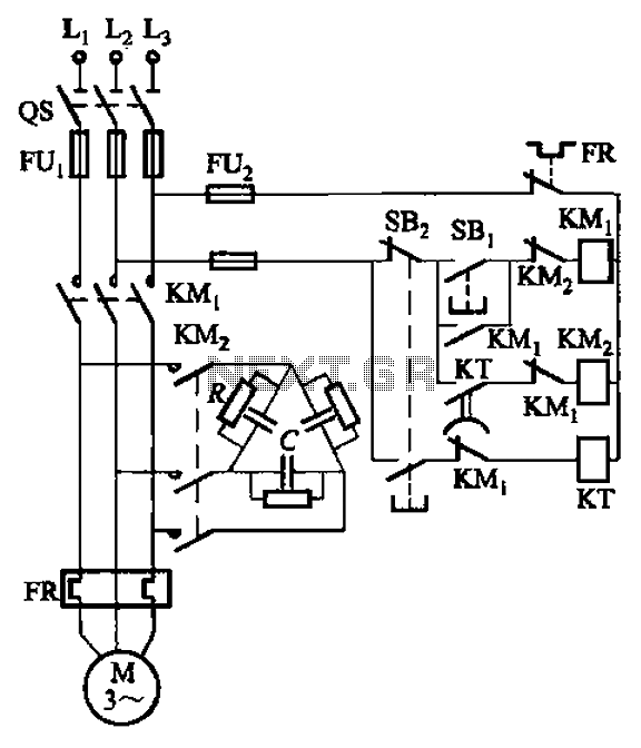
The circuit illustrated in Figure 3-151 consists of capacitor banks arranged in a specific configuration. Figure 3-151 (a) depicts capacitor banks connected in a shaped manner, which is suitable for use with shaped or Y-connected motors. Figure 3-151 (b)...
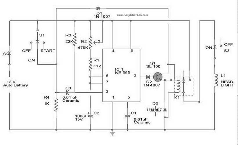
The circuit diagram for the automatic headlights turn-off circuit is presented here. This circuit can be installed in a car. The automatic headlights turn-off circuit is designed to enhance vehicle safety and convenience by ensuring that the headlights are automatically...