
The Accelerometer Circuit

The schematic consists of the following key components: the ADXL320 accelerometer, the PIC microcontroller, and an LED indicator. The ADXL320 sensor is a three-axis accelerometer capable of providing analog output signals corresponding to acceleration along the X, Y, and Z axes. The output signals are fed into the PIC's A/D converter inputs.
The PIC microcontroller is programmed to continuously sample the analog voltage signals from the ADXL320. The software will convert these analog values into digital representations that correspond to the acceleration forces acting on the sensor. By analyzing these values, the microcontroller determines the tilt angle or the rate of acceleration.
The LED is connected to one of the output pins of the PIC. The blinking frequency of the LED is modulated based on the processed acceleration data. For instance, a higher acceleration detected by the ADXL320 will result in a faster blinking rate of the LED, while lower acceleration will cause a slower blink. This visual feedback provides an intuitive way to observe the sensor's response to motion.
The power supply circuitry must ensure that the PIC receives a stable +5V supply. This can be achieved using a simple battery configuration or a more complex power management circuit, depending on the application requirements. Proper decoupling capacitors should be included near the power pins of the PIC and ADXL320 to filter any noise and ensure stable operation.
Overall, this circuit provides a basic yet effective demonstration of interfacing an accelerometer with a microcontroller, showcasing how sensor data can be processed and represented visually through an LED indicator.The schematic is very simple for this tutorial. It is just a matter of wiring up the ADXL320 sensor to the PIC and the LED. The power circuitry assumes you have a battery of +5v to power the PIC. You can create your own custom circuitry for this or just use a battery array. whatever you like. The PIC is the brains of the circuit. Using the A/D`s on the PIC data samples will be taken as input and then evaluated. Based off different inputs the LEDs will blink faster or slower to show how much the board has been tilted or accelerated. This sensor will output an analog signal to the PIC to be interpreted. The signal is measured by its change in voltage when you want to find out how many g`s are currently being `pulled`.
This is just one single LED added to the circuit. Depending on how fast it is blink will tell us how much acceleration or tilt is being applied to the ADXL320 sensor. This will of course all be done in software in the PIC. 🔗 External reference
Related Circuits
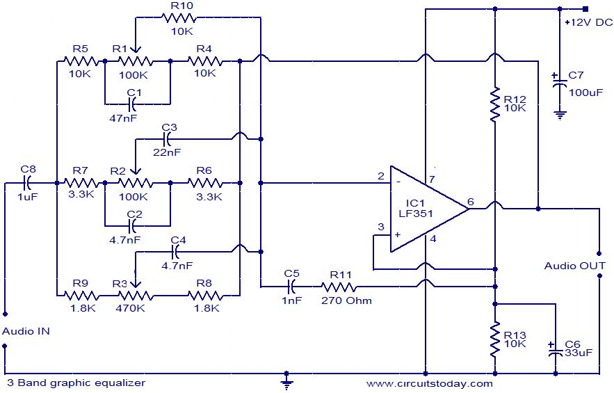
This document presents the circuit diagram of a simple three-band graphic equalizer that utilizes a single integrated circuit (IC) and a few additional components. The IC employed in this design is the LF351, which is a wide bandwidth single...
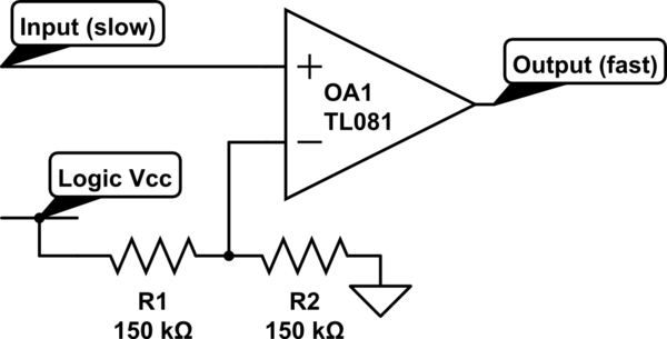
Invert a signal to drive FETs with rapid rise and fall times. It was suggested to use an inverter (not a chip) instead of logic chips, which are designed to be either fully ON or OFF. The individual has...
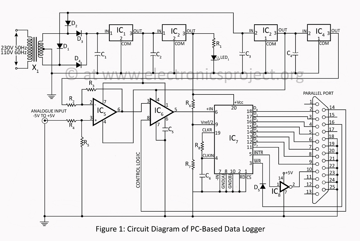
A PC-based data logger utilized in physics laboratories for automating simple experiments and monitoring slowly varying physical variables across various PC-based projects. The PC-based data logger serves as an essential tool in physics laboratories, enabling the automation of experiments and...
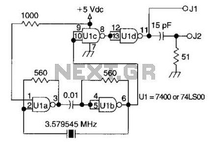
A circuit utilizing one 7400 TTL can operate with fundamental type crystals ranging from 1 to approximately 13 MHz. The output is rich in harmonics, making this oscillator suitable for calibration and testing applications. The circuit in question employs a...
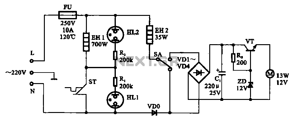
The electric thermos temperature detection control circuit is designed to monitor and manage the temperature within an electric thermos. It primarily consists of a control circuit for the boiler heater and heater insulation, an electrical magnetic pump motor drive...
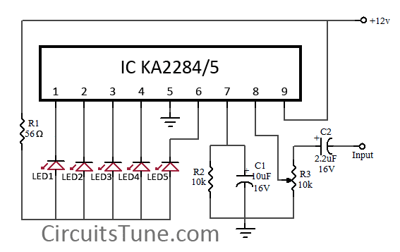
This is a simple circuit diagram of a 5-LED audio VU meter utilizing the ICs KA2284 or KA2285. The KA2284 and KA2285 are monolithic integrated circuits designed as logarithmic display driver ICs. They serve as bar-type display drivers for...