
Three Stage Sequential Timer Circuit

The circuit described utilizes three 555 timer integrated circuits (ICs) configured to generate three sequential output pulses. The 555 timer operates in monostable or astable modes, and in this configuration, it is likely set up in a monostable mode for each of the three timers.
In this arrangement, the output of the first 555 timer is connected to the trigger input of the second 555 timer. When the first timer is triggered, it generates a pulse that activates the second timer. Similarly, the output of the second timer is connected to the trigger input of the third timer, thereby allowing for a cascading effect where each timer sequentially activates the next.
To achieve astable operation, the third 555 timer's output can be connected back to its trigger input. This feedback loop enables continuous oscillation, producing a square wave output. The frequency and duty cycle of the output pulses can be controlled by adjusting the resistors and capacitors connected to each 555 timer.
The output from each timer can be used in various applications, such as generating clock signals for digital circuits, controlling timing sequences in automation systems, or creating sound signals in audio applications. Proper selection of component values is crucial for achieving the desired pulse width and frequency for each stage of the circuit.
Overall, this configuration of 555 timers provides a versatile solution for generating sequential pulses and can be adapted for various electronic applications. By using three 555 ICs, three sequential pulses can be generated. Output 3 can be connected back to trigger input to achieve astable operation.
Related Circuits
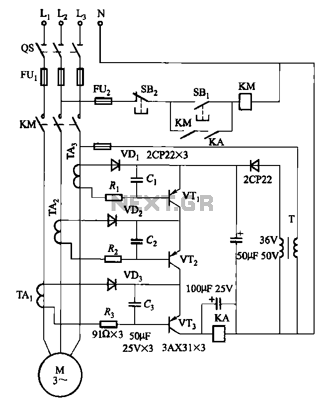
Drawing transistors that comprise the gate VTi, VT2, VT3, and similar components. The schematic involves a configuration of transistors designated as VTi, VT2, and VT3, which are integral to forming a gate structure. These transistors are typically arranged in a...

The Mini AV Test Box circuit is designed with simplicity and efficiency in mind. It consists of three main sections, which are clearly delineated in the schematic. The primary components utilized in this circuit include the 7805 voltage regulator,...
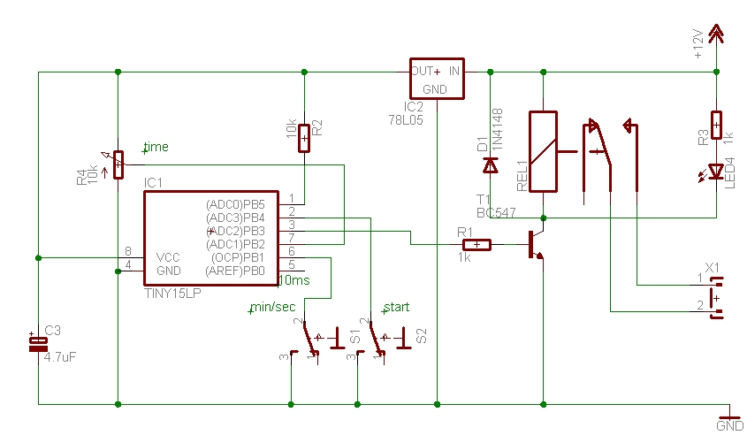
The time can be set using a potentiometer ranging from 1 minute to 1023 minutes, approximately 17 hours. A pushbutton initiates the timing process, activates a relay, and the timer will deactivate the relay once the set time has...
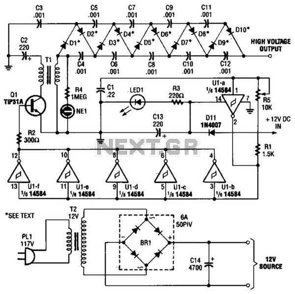
In the miniature high-voltage DC generator, the circuit receives input from a 12 V DC power supply, which is amplified to produce a 10,000 V DC output. This process induces a pulsating signal of opposite polarity in the secondary...

This circuit design generates a stable 1 kHz sine wave using an inverted Wien bridge configuration with components C1-R3 and C2-R4. It offers a variable output, low distortion, and low output impedance to ensure good overload capability. The circuit...
MP3 players are very popular today, especially the smaller memory-stick formats that are easy to transport, allowing for personal sound systems on the go. However, when sharing music with others, these players often lack sufficient power. The MP3 booster...