
USB-Powered PIC Programmer

The circuit operates by leveraging the 555 timer in astable mode, which generates a continuous square wave output. This output is essential for driving the Cockcroft-Walton voltage multiplier, which consists of capacitors and diodes arranged to step up the input voltage to the required programming level for the PIC microcontroller. The 1N4148 diodes are selected for their fast switching capabilities, allowing for efficient rectification of the AC waveform produced by the 555 timer.
The Cockcroft-Walton multiplier's design ensures that the voltage is increased effectively while maintaining stability. The arrangement of four stages (capacitors and diodes) allows the circuit to achieve the necessary output voltage, which is critical for programming operations. The output voltage is then routed through the optocoupler, which provides electrical isolation between the programming circuit and the microcontroller, enhancing safety and protecting the PIC from potential overvoltage damage.
Zener diodes ZD1 and D5 serve a crucial function by clamping the output voltage to a maximum of 13.6V, preventing the MCLR/Vpp pin from exceeding its specified limits. This is important for maintaining the integrity of the programming process and ensuring the longevity of the microcontroller. The 100kΩ resistor connected to the MCLR/Vpp pin ensures that the pin is pulled low when not in use, preventing accidental triggering of the programming mode.
Overall, this circuit provides a cost-effective and reliable solution for programming PIC16F84 microcontrollers and similar devices, making it suitable for hobbyists and professionals alike. Its compatibility with software like ICProg further enhances its utility, allowing for easy integration into various programming workflows.This simple circuit can be used to program the PIC16F84 and similar "flash memory" type parts. It uses a cheap 555 timer IC to generate the programming voltage from a +5V rail, allowing the circuit to be powered from a computer`s USB port. The 555 timer (IC1) is configured as a free-running oscillator, with a frequency of about 6. 5kHz. The output of the timer drives four 100nF capacitors and 1N4148 diodes wir-ed in a Cockroft-Walton voltage multiplier configuration. The output of the multiplier is switched through to the MCLR/Vpp pin of the PIC during programming via a 4N28 optocoupler.
Diodes ZD1 and D5 between the MCLR/Vpp pin and ground clamp the output of the multiplier to about 13. 6V, ensuring that the maximum input voltage (Vihh) of the PIC is not exceeded. A 100k © resistor pulls the pin down to a valid logic low level (Vil) when the optocoupler is not conducting.
The circuit is compatible with the popular "JDM" programmer, so can be used with supporting software such as "ICProg" (see ). 🔗 External reference
Related Circuits
C0QBmk~%24(KGrHqIOKkIEq4M%2Bu,)1BK2zHH580Q~~_35.gif)
This time, information will be shared about the schematics of radios, specifically the schematic of a programmer radio, along with the latest information available on Onmilwiki. The schematic of a programmer radio typically includes various components essential for its operation,...
If a page name is not selected by pressing the button, the previously selected page name continues to be used. The value is stored in EEPROM and may be changed at any time. When the unit is first powered...
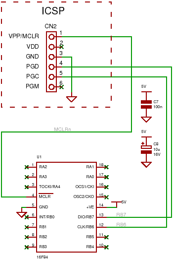
An introduction to the PIC16F84 microcontroller, including connections for an ICSP programmer and a circuit example. The PIC16F84 is an 8-bit microcontroller from Microchip Technology, widely utilized in various embedded applications due to its versatility and ease of use. It...
The circuit comprises a Microchip PIC 16F84 microcontroller and an LCD text module. The author claims that this counter can measure frequencies ranging from 400 Hz to 50 MHz. A faster version, the 20 MHz PIC 16F84A-20I/P, was utilized,...
This is a simple servo tester which will comprehensively test the capabilities of almost any modern servo. It has two pushbuttons, CENTRE and SWEEP and a potentiometer which works as follows: - CENTRE Does exactly that, centers the servo,...
A source code for a simple PIC-based digital timer is provided. The hardware for the project is not available; however, it will be demonstrated using a DIY PIC16F628A breadboard module and I/O board. The complete circuit diagram and firmware...