
Simple Intercom Circuit

The intercom circuit operates using the LM380 audio power amplifier, which is designed to provide sufficient audio output for communication between two parties. The circuit configuration includes a switch that toggles between two states: talk and listen. In the talk position, the microphone captures the speaker's voice and amplifies it through the LM380, allowing the left speaker to transmit audio to the listener. The listener's speaker receives this amplified signal, enabling clear communication.
When the listener wants to respond, the switch must be toggled to the talk position, allowing the listener to speak into their microphone while the left speaker becomes the listener. This requires both users to actively manage the switch to facilitate a two-way conversation.
The grounding of pins 3, 4, 5, 10, 11, and 12 is crucial for the stability and performance of the LM380, ensuring that the amplifier operates within its specified parameters. Proper grounding minimizes noise and interference, which is essential for maintaining audio clarity during conversations.
The circuit design may include additional components such as capacitors for filtering and resistors for setting gain levels, which contribute to the overall functionality and performance of the intercom system. Careful attention to these details will enhance the user experience by improving sound quality and reliability in communication.This is simple intercom circuit. Here I have used common Ic LM380. Now the switch is in the talk position for the speaker on the left, And the other persons position is listening position. If other one wants to speak The switch must be change to another position. (Both users should do that). Pins 3, 4, 5, 10, 11, 12 are grounded. 🔗 External reference
Related Circuits
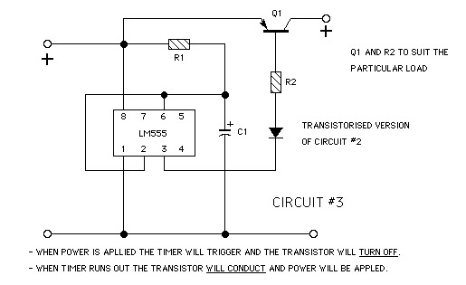
The goal is to create a small light that is activated by motion and stays illuminated for 20 seconds before turning off. For example, when the light is picked up, it illuminates, and when placed back down, it remains...
Each zone uses a normally closed contact. These can be micro switches or standard alarm contacts (usually reed switches). Zone 1 is a timed zone which must be used as the entry and exit point of the building. Zones...
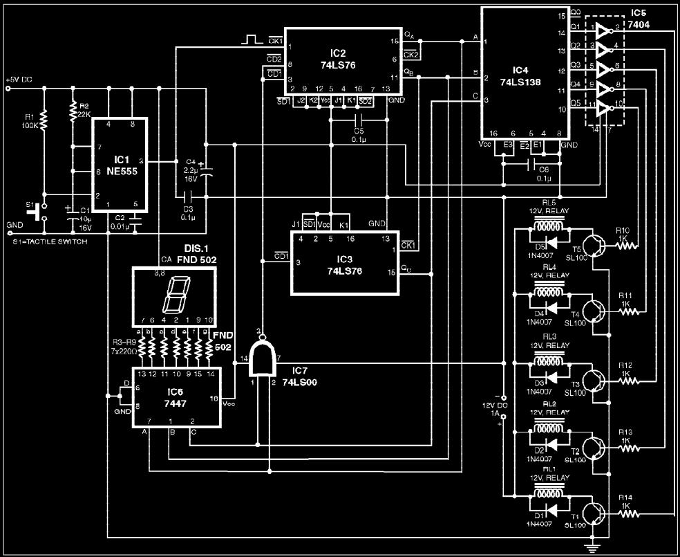
The circuit presented is a digital fan regulator that offers five speed levels, similar to conventional fan regulators. This ceiling fan controller utilizes readily available components. An optional 7-segment display with associated circuitry is included to show the selected...
As a cyclist, there is a constant search for methods to enhance visibility during nighttime rides. The concept of the `NITE-RIDER` was developed to create a distinctive and attention-grabbing rear light for bicycles. This design features nine extra-bright LEDs...
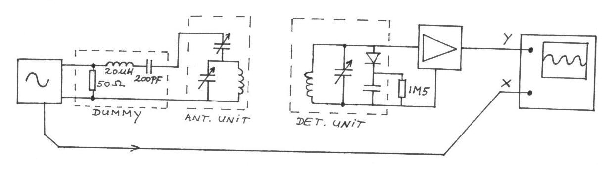
The frequency remains constant, oscillating between two predetermined values. On the oscilloscope display, a frequency spectrum is observed, showcasing the response curves of the two circuits. The input voltage of the receiver is 0.1 Volt peak-to-peak, while the voltage...
In the silicon-controlled trigger circuit, a cadmium sulfide cell is connected to a relaxation oscillator, which serves as a sensor to activate a blinking light in a darkroom. This setup causes a speaker to emit a warning sound of...