
Colorful lights loop circuit

The described circuit is designed to convert 220 V AC into a stable 12 V DC output, suitable for powering various electronic devices. The process begins with the C1 buck converter, which steps down the high voltage AC to a lower voltage level. The DW regulator then stabilizes this voltage, ensuring that the output remains consistent despite variations in input voltage or load conditions.
The VD component acts as a rectifier, converting the AC voltage into a pulsating DC voltage. Following this, capacitor C2 filters the output, smoothing the pulsating DC into a more stable and usable 12 V DC supply. This output is critical for the voltage supply control circuit, which regulates the power delivered to downstream components.
The NE555 integrated circuit (IC1) serves as a versatile timer and pulse generator, essential for creating clock signals. The configuration of resistors R1 and Rp, along with capacitor C3, allows for the adjustment of the frequency and duty cycle of the output pulse. This flexibility makes it suitable for various applications where timing and control are necessary.
The adjustable clock pulse generator provides the required clock signals for the subsequent stages of the circuit, ensuring synchronized operation of all components. This feature is particularly useful in applications such as motor control, signal processing, and timing applications, where precise timing is crucial for functionality. Overall, this circuit design demonstrates an effective approach to power conversion and control using standard electronic components.Circuit works: 220 V AC by C1 Buck, DW regulator, VD whole stream, C2 filtered output 12 V DC voltage supply control circuit. IC1 time base integrated circuit NE555 and R1, Rp, C3 composed of an adjustable clock pulse generator for providing clock signals required post-stage circuit.
Related Circuits
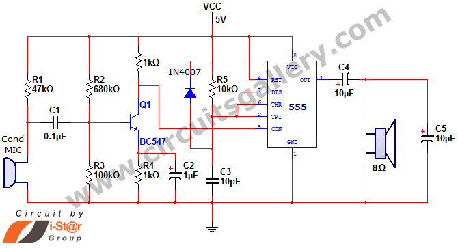
This document discusses a simple project utilizing the 555 timer IC. The 555 timer IC can be configured as an audio amplifier using an astable multivibrator configuration. It performs pulse width modulation (PWM) on an audio signal. The current...
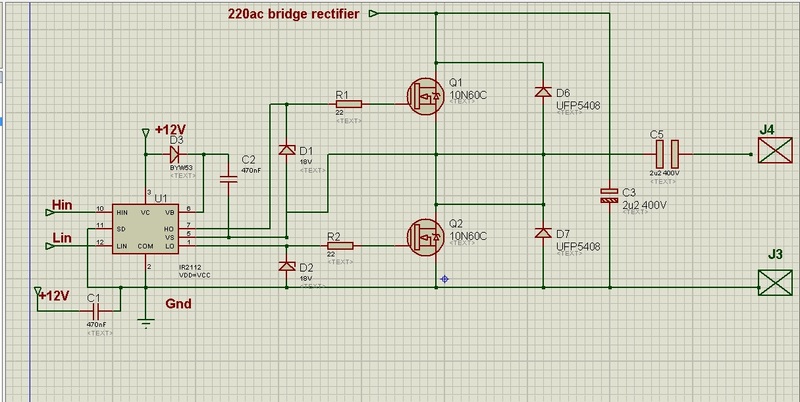
This circuit is designed to drive an ultrasonic transducer. A question has arisen regarding how to limit the output current, as a 60W transducer may be at risk of damage due to excessive current. Guidance or examples for integrating...
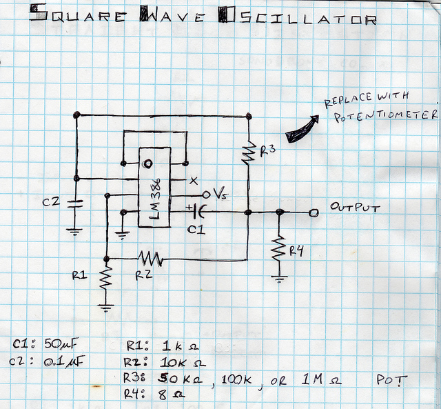
This is a square wave oscillator (digital, similar to 8-bit music). It is based on the LM386 amplifier integrated circuit, which is also the foundation for the mini guitar amplifier. The design includes a simple power switch connected to...
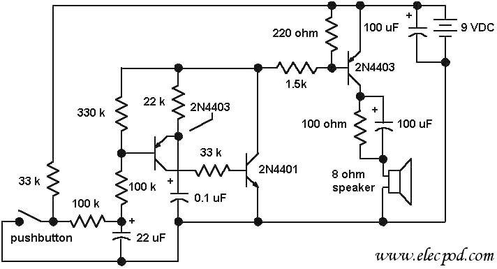
The core component of the circuit is a dual transistor flasher with frequency modulation applied to the base of the first transistor. When the pushbutton is pressed, the oscillation frequency increases to a peak, and when the button is...
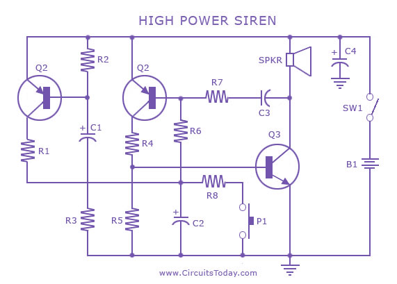
A siren circuit diagram that generates a strong, high-power siren or alarm sound using complementary transistor pairs BC 557 and BC 337, arranged as an oscillator. The described siren circuit employs a pair of complementary transistors, BC 557 (a PNP...
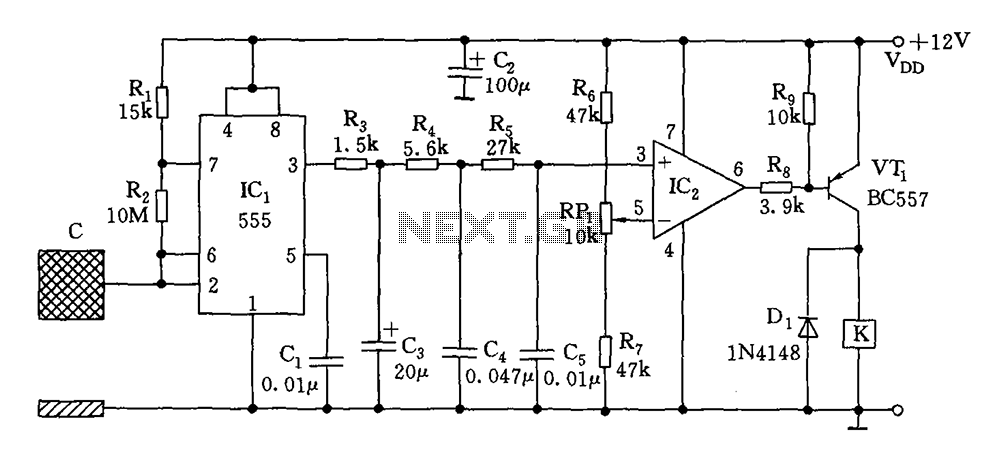
The switch circuit consists of a capacitive oscillator, an integration network, and a comparator circuit that controls a relay. When a body comes close to the induction plate, the inductive capacitance to ground increases, causing the 555 astable multivibrator...