
AC Motor Speed Controller

The AC Motor Speed Controller operates by adjusting the voltage and current supplied to the motor, effectively changing its speed. This control is achieved through the use of various electronic components, including triacs, diodes, and resistors, which work together to modulate the power delivered to the motor.
In a typical schematic, the controller includes an input section where the AC supply is connected. This input is often filtered to remove noise and ensure stable operation. The core of the controller consists of a phase control circuit, typically utilizing a triac to control the power flow. The triac is triggered by a gate signal, which can be adjusted based on the desired speed setting.
A potentiometer may be included as part of the user interface, allowing the operator to set the desired speed. This potentiometer adjusts the timing of the triac's firing angle, effectively controlling the amount of power reaching the motor. Additionally, a microcontroller may be integrated to provide more advanced control features, such as soft start, overload protection, and speed feedback.
The output section of the controller connects directly to the AC motor, ensuring that the modified voltage and current are delivered efficiently. Safety features, such as fuses or circuit breakers, are often included to protect against overload conditions.
Overall, the AC Motor Speed Controller provides an effective solution for varying the speed of AC motors in a range of applications, enhancing versatility and performance in tools and appliances.AC Motor Speed Controller was designed to control the speed of AC motors with carbon brushes anything from drills to saws to vacuum cleaner.. 🔗 External reference
Related Circuits
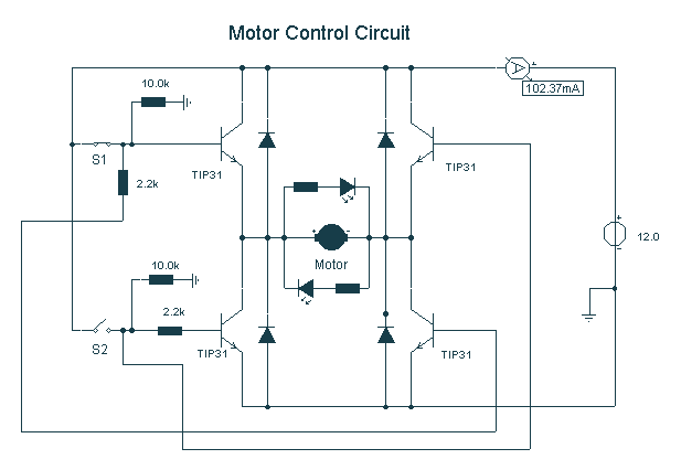
Here, S1 and S2 are normally open, push to close, press button switches. The diodes can be red or green and are there only to indicate direction. You may need to alter the TIP31 transistors depending on the motor...
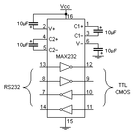
Standard serial interfacing of a microcontroller (TTL) with a PC or any RS232C standard device requires a TTL to RS232 level converter. A MAX232 is used for this purpose. It provides a 2-channel RS232C port and requires external 10µF...

Connect a transformer to the motor phase line when the induced voltage is zero volts. In cases of serious imbalance in one, two, or three phases, the transformer’s induced voltage increases rapidly, which leads to an immediate rectification of...
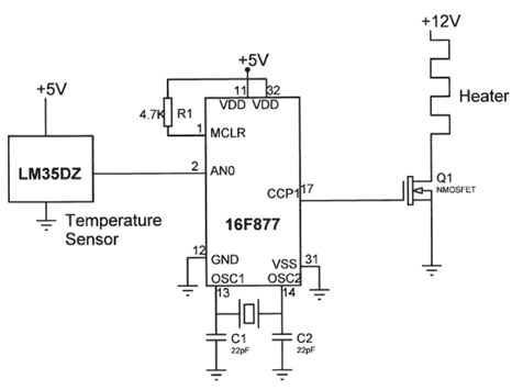
The electrical circuit diagram of this temperature control circuit consists of a 3-pin analog temperature sensor (LM35DZ), a built-in A/D converter microcontroller (PIC16F877), and the heater driver (IRL1004). The temperature control circuit utilizes the LM35DZ, a precision analog temperature sensor...
An IR remote control is a widely used device found with televisions, VCRs, and home theaters. It can also be utilized to control personal devices such as lights and air conditioning. Remote controls operate using infrared (IR) light, which...
The circuit operates by using a clock signal to drive four D-flip-flops in the control section, which store the on/off state of each current direction for the two stepper motor coils. The flip-flops create a finite state machine (FSM)...