
A three-phase motor phase automatic protection circuit

This circuit employs a transformer to monitor the voltage levels across the motor phase lines. When the induced voltage drops to zero, indicating a potential fault condition or imbalance in the power supply, the transformer triggers a series of actions to protect the motor. The rapid rise in induced voltage during an imbalance condition is detected and processed, resulting in the rectification of the base current of a transistor.
The transistor is configured to operate in a switching mode. Once the base current reaches a certain threshold due to the rectification process, the transistor enters saturation, allowing current to flow through the relay coil. Relay K is used to control the power supply to the motor by operating its normally closed contact. Under normal conditions, this contact allows current to flow to the contactor coil, keeping the motor operational.
However, when the relay is activated due to the transistor's saturation, the normally closed contact opens, interrupting the power supply to the contactor coil. This action effectively de-energizes the coil, resulting in the disconnection of power to the motor. The circuit is designed to respond quickly, with an operating time of less than one second, ensuring that the motor is promptly stopped in the event of a serious phase imbalance, thereby preventing potential damage to the motor or associated equipment.
Overall, this circuit serves as a protective measure for motors operating in environments where phase imbalances may occur, ensuring reliable operation and safety.Penetrate the motor phase line with a transformer when the induced voltage is ov. When one phase or two-phase or three-phase serious imbalance, transformer induced voltage rises rapidly, resulting in the transistor base current after rectified immediately transistor saturated conduction, the relay K was electric suction units, normally closed contact off point, the contactor coil is oFF, touch -break, loss of power the motor stops running. Operating time is less than 1 second.
Related Circuits
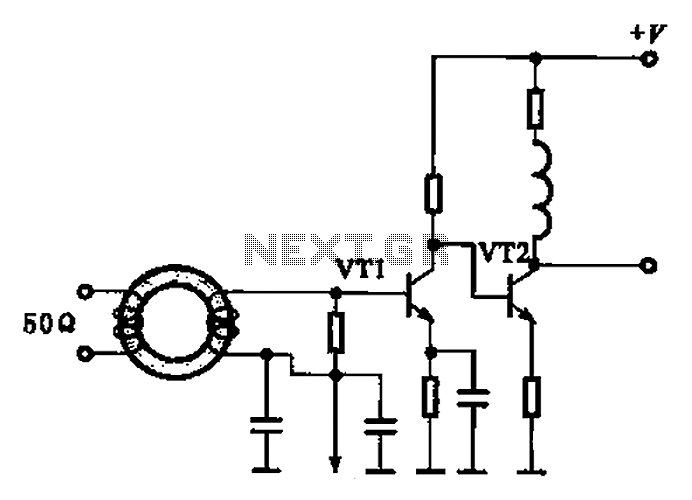
A broadband high-frequency amplifying circuit is primarily composed of a high-frequency matching transformer and an amplifying transistor. This circuit is designed to handle large high-frequency signals. The input of the amplifier circuit utilizes a matching transformer to ensure that...

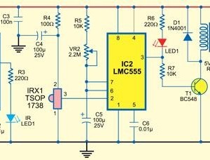
Construct a temperature controller circuit using the 555 integrated circuit (IC) in combination with a thermistor resistor divider. The benefit of this design is that it does not require a well-regulated power supply. The resistor divider network comprises an...
This type of infrared proximity circuit is commonly utilized as an electric switch where physical contact is undesirable for hygiene reasons. For instance, infrared proximity sensors are frequently found in public drinking fountains and washrooms. The straightforward circuit described...
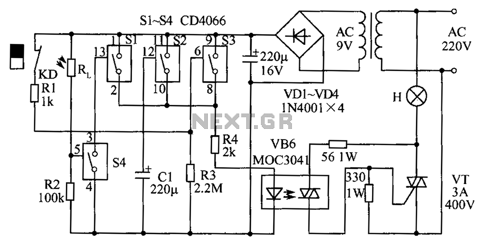
The circuit diagram illustrates a group of four analog electronic circuit switches (S1 to S4). Switches S1, S2, and S3 are utilized in a parallel delay circuit. When the power is activated, resistor R4 drives the triac VT, which...
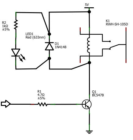
The BC547B transistor has a collector-base voltage (Vcbo) of 50V, a collector-emitter voltage (Vceo) of 45V, and an emitter-base voltage (Vebo) of 6V. In contrast, the BC548 transistor in the original circuit has a Vcbo of 30V, a Vceo...
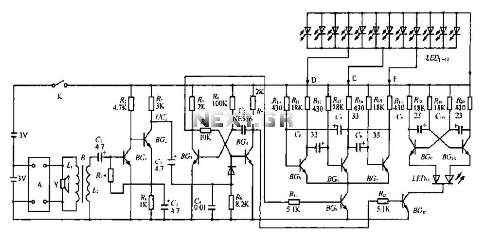
The BGl and BG2 form a directly coupled amplifier, while BG and BG4 consist of a monostable trigger circuit. Without receiving a prior trigger signal, BG3 enters a saturated conduction state. During this steady state, the collector of BG4...