DC Motor Control Circuit
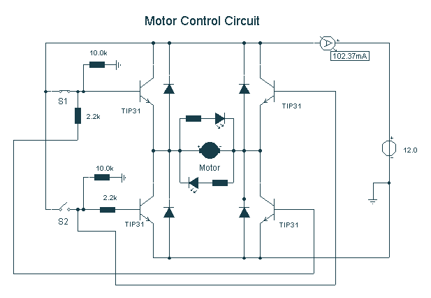
Here, S1 and S2 are normally open, push to close, press button switches. The diodes can be red or green and are there only to indicate direction. You may need to alter the TIP31 transistors depending on the motor being used. Remember, running under load draws more current. This circuit was built to operate a small motor used for opening and closing a pair of curtains. As an advantage over automatic closing and opening systems, you have control of how much, or how little light to let into a room. The four diodes surrounding the motor are back EMF diodes. They are chosen to suit the motor. For a 12V motor drawing 1 amp under load, I use 1N4001 diodes.
The described circuit utilizes two normally open push-button switches, S1 and S2, which serve as user controls for operating a small motor responsible for opening and closing curtains. When either switch is pressed, it completes the circuit, allowing current to flow and activating the motor. The configuration permits the user to control the position of the curtains, providing flexibility in managing light levels within a room, unlike fully automated systems.
The circuit incorporates diodes, which may be red or green for visual indication of the direction of motor operation. These diodes are essential for ensuring that the current flows in the intended direction and provides feedback to the user regarding the state of the circuit.
The use of TIP31 transistors is crucial for switching the motor on and off, and it is important to select transistors that can handle the current requirements of the specific motor being utilized. The TIP31 is a power transistor that can manage higher currents, but it may need to be substituted based on the motor's specifications, especially if the motor operates under load, which increases the current draw.
Back EMF diodes are integrated into the circuit to protect the transistors from voltage spikes generated when the motor is turned off. These spikes can damage the transistors if not properly managed. The choice of diodes, such as the 1N4001, is appropriate for a 12V motor drawing 1 amp under load, as they are rated for sufficient reverse voltage and current handling.
Overall, this circuit design provides a practical solution for controlling a small motor in a curtain application, combining user control with protective measures to ensure reliable operation.Here, S1 and S2 are normally open , push to close, press button switches. The diodes can be red or green and are there only to indicate direction. You may need to alter the TIP31 transistors depending on the motor being used. Remember, running under load draws more current. This circuit was built to operate a small motor used for opening and closing a pair of curtains. As an advantage over automatic closing and opening systems, you have control of how much, or how little light to let into a room. The four diodes surriunding the motor, are back EMF diodes. They are chosen to suit the motor. For a 12V motor drawing 1amp under load, I use 1N4001 diodes. 🔗 External reference
