
AC-SSR application circuit

The AC solid-state relay (AC-SSR) is an electronic switching device that utilizes semiconductor components to perform the switching operation, eliminating the mechanical parts found in traditional electromechanical relays. This results in improved reliability, faster switching times, and a longer operational lifespan. The basic application circuit for the AC-SSR typically involves a control input that activates the relay, allowing it to conduct AC power to the load.
The TTL drive SSR circuit (Figure b) employs a Transistor-Transistor Logic (TTL) signal to control the relay. TTL circuits are known for their high-speed operation and low power consumption, making them suitable for interfacing with microcontrollers and digital systems. This configuration typically includes a series resistor to limit the current into the input of the SSR, ensuring that the control signal is within acceptable levels for reliable operation.
In the CMOS driver circuit (Figure c), Complementary Metal-Oxide-Semiconductor (CMOS) technology is utilized to provide a high input impedance and low power consumption. This type of driver is particularly advantageous in battery-powered applications where energy efficiency is critical. The circuit may include pull-up or pull-down resistors to stabilize the input signal and prevent floating states.
The thyristor drive circuit (Figure d) uses thyristors to control the AC load. Thyristors are semiconductor devices that can handle high voltages and currents, making them suitable for heavy-duty applications. The circuit typically includes a gate control mechanism to trigger the thyristor, allowing it to switch on and off in response to the control signal. This type of drive is often employed in applications requiring precise control of AC power, such as motor control and lighting systems.
Overall, the various drive circuits for the AC solid-state relay provide flexibility in design and application, catering to different operational requirements and system architectures.About solid (body) relay AC solid state relay (AC-SSR) of the basic application circuit shown in Figure (a) below; With TTL drive SSR circuit is shown in (b) below; SSR with CMOS driver circuit is shown in (c) below; SSR thyristor drive circuit shown in (d) below.
Related Circuits
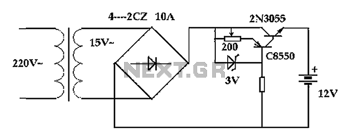
The circuit operates after a transformer, utilizing a bridge rectifier and conditioning for battery charging. The charging current transformer can be easily adjusted to provide approximately 12V at 100Ah battery charging. The required charging current is 10A, and a...
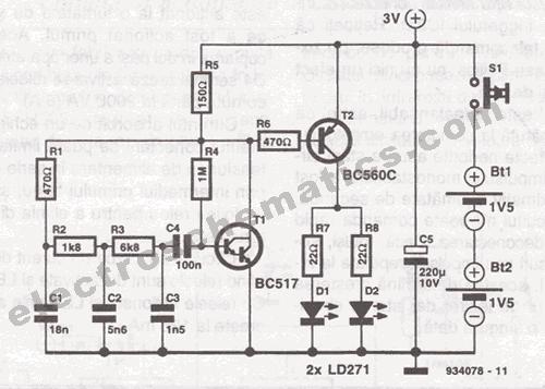
This infrared transmitter is designed for use with an infrared receiver. It operates using either two 1.5V batteries or a 3V lithium battery, allowing for a compact infrared communication system. The infrared transmitter circuit typically consists of an infrared LED,...
More: The input data lacks specific content, providing only placeholders without any detailed information. In the context of electronic schematics, a comprehensive description typically involves detailing the components, their interconnections, and the overall functionality of the circuit....
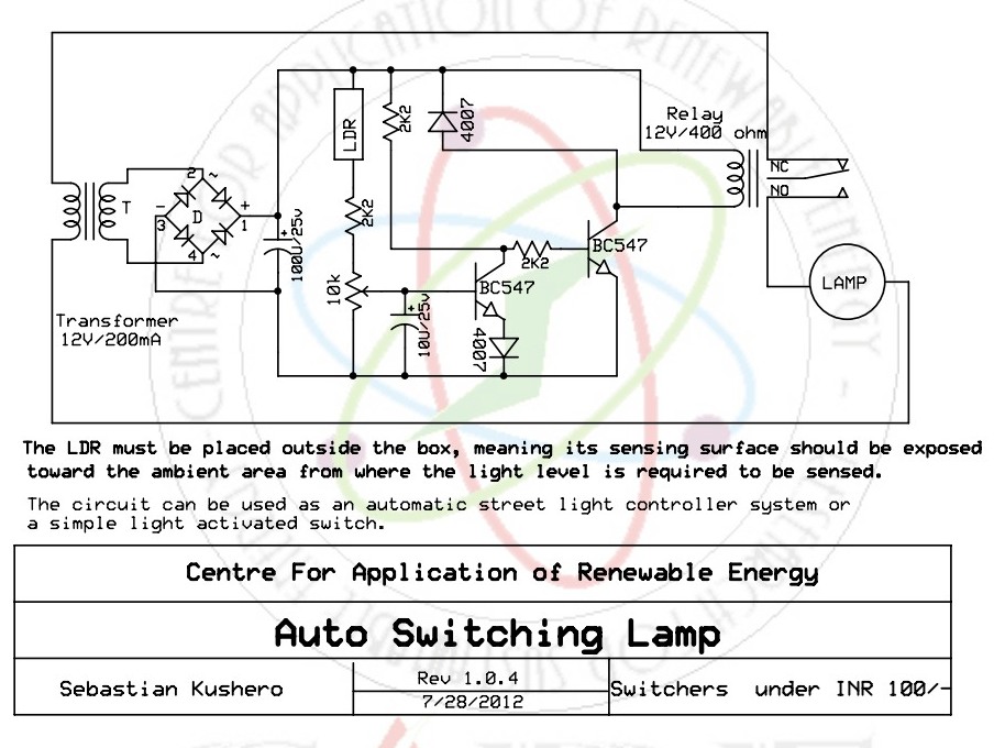
This sound-activated switch allows for sound control, which can be beneficial not only for robotic applications but also for home automation. The sound-activated switch operates by detecting specific sound frequencies or patterns, enabling the user to control various devices or...
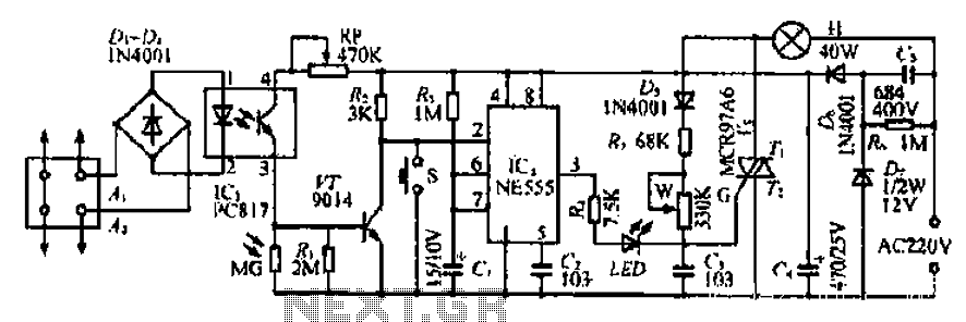
The Ai. A2 series operates with a telephone line, where sound anomalies or off-hook currents activate a light within an arc tube, which in turn triggers a photosensitive MOSFET. This process involves a saturated conduction base voltage that sends...
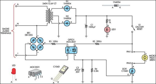
This alarm circuit is designed to monitor a mains-powered smoke detector located in a shed used for dog kennels. It ensures complete isolation from the mains, allowing low-voltage (12V) cabling to connect to the alarm circuit situated inside the...