
Sound Activated Switch Circuit

The sound-activated switch operates by detecting specific sound frequencies or patterns, enabling the user to control various devices or systems with voice commands or other sound inputs. The core component of this circuit typically includes a microphone or sound sensor, an amplifier, and a microcontroller or logic circuit that processes the sound signals.
The microphone captures ambient sound and converts it into an electrical signal. This signal is then amplified to a suitable level for further processing. The amplified signal is fed into a microcontroller, which is programmed to recognize specific sound patterns or thresholds. Upon detecting the designated sound, the microcontroller can trigger an output, which may be used to activate a relay, switch on a light, or control other electronic devices.
In a home automation context, this technology can be integrated into various applications such as turning on lights, controlling appliances, or even activating security systems. The versatility of sound-activated switches makes them a valuable addition to both robotic systems and home automation setups, enhancing user interaction and convenience.
For optimal performance, careful consideration should be given to the selection of the microphone, the sensitivity settings of the amplifier, and the programming of the microcontroller to ensure reliable operation in various acoustic environments. Additionally, incorporating noise filtering techniques can improve the accuracy of sound detection, minimizing false activations from background noise.With this sound activated switch, control by sound may be very useful, not just on a robot but also for a bit of home automation, for example a sound-activ.. 🔗 External reference
Related Circuits
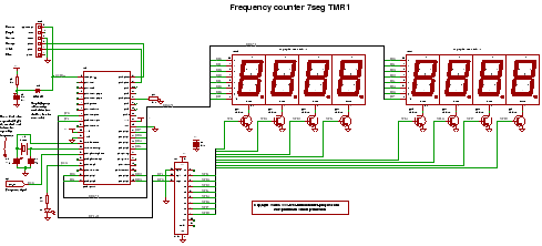
C code for a frequency counter circuit operating up to approximately 50 MHz, utilizing a multiplexed seven-segment display and employing Timer 1 to count the edges of the input signal. The frequency counter circuit described operates effectively within the range...
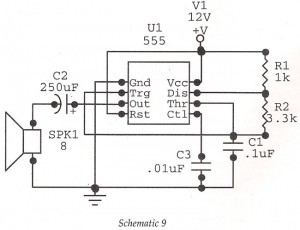
This circuit features an astable oscillator constructed around a 555 timer, generating an alarm tone of 1.8 kHz, which directly drives a speaker. It serves as a fundamental alarm circuit that can be utilized in various projects. Although the...
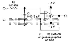
This simple filter utilizes an RC section as the filter element, incorporating a voltage follower to manage other frequencies. The -3 dB point is calculated as 1/(6.28 * RXCV), resulting in a response that drops 6 dB per octave...
As with the Electronic sel. 8 we also have here a circuit with a choice of 8 different sources. The difference is that only two of the switches are used and the movement of commands is Up-Down in series....
This is a police tone circuit for a siren. It is simple and easy to construct. VR1 and VR2 are used to adjust the delay of the siren sound. The design is straightforward and uncomplicated. The police tone siren circuit...
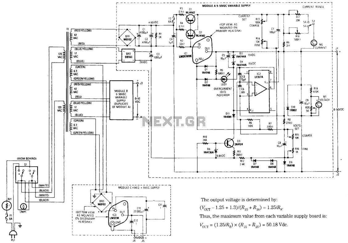
The design's value is derived from the use of IC1, an LM317HVK adjustable series-pass voltage regulator, which provides broad-range performance along with voltage-setting and current-limiting functions. The input to IC1 is sourced from the output of BR1, which is...