
Accurate Low-Cost Square-Root Converter

The low-cost accurate square-root circuit typically employs operational amplifiers (op-amps), resistors, and diodes to achieve its functionality. The primary objective of this circuit is to convert an input voltage, representing a squared value, into its square root equivalent, thereby facilitating various applications in analog computing and signal processing.
The circuit design may start with a basic op-amp configuration, where the input voltage is applied to the non-inverting terminal. A feedback network composed of resistors can be utilized to establish the gain required for accurate square-rooting. Diodes may be incorporated to ensure that the output remains within the desired voltage range and to provide temperature stability, enhancing the overall accuracy of the circuit.
The output voltage, which represents the square root of the input voltage, can be further refined using additional filtering stages to minimize noise and improve signal integrity. The performance of the circuit can be evaluated by measuring the output against known square values, ensuring that the deviation from expected results remains within acceptable limits.
Applications for this square-root circuit include analog signal processing in instrumentation systems, control systems, and any scenario where a square-root function is required, such as in calculating distances in sensor applications. The low-cost nature of this circuit makes it particularly attractive for educational purposes and prototype development, allowing users to explore mathematical functions without significant financial investment.This is a Low-Cost Accurate Square-Root Circuit. This circuit is used to provide a square-root function with a good accuracy. The benefit of This circuit is. 🔗 External reference
Related Circuits
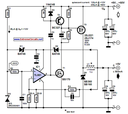
This circuit was developed to provide a 5 V output from the 24 V battery of a solar-powered generator. The circuit is designed to efficiently step down the voltage from a 24 V source to a stable 5 V...
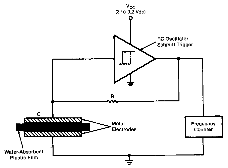
The sensor operates as an RC oscillator, utilizing a water-absorbent plastic film as the insulator within the capacitive element. The capacitance of this film increases with the amount of water it absorbs from the air, resulting in a reduction...
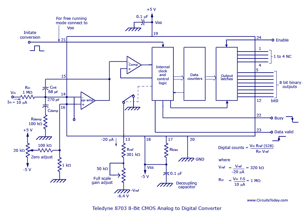
The basic analog to digital (A/D) converter circuit has been previously explained. In addition to this, various types of monolithic analog to digital converters exist, including the integrating A/D, integrating A/D with three-stage outputs, and the tracking A/D with...
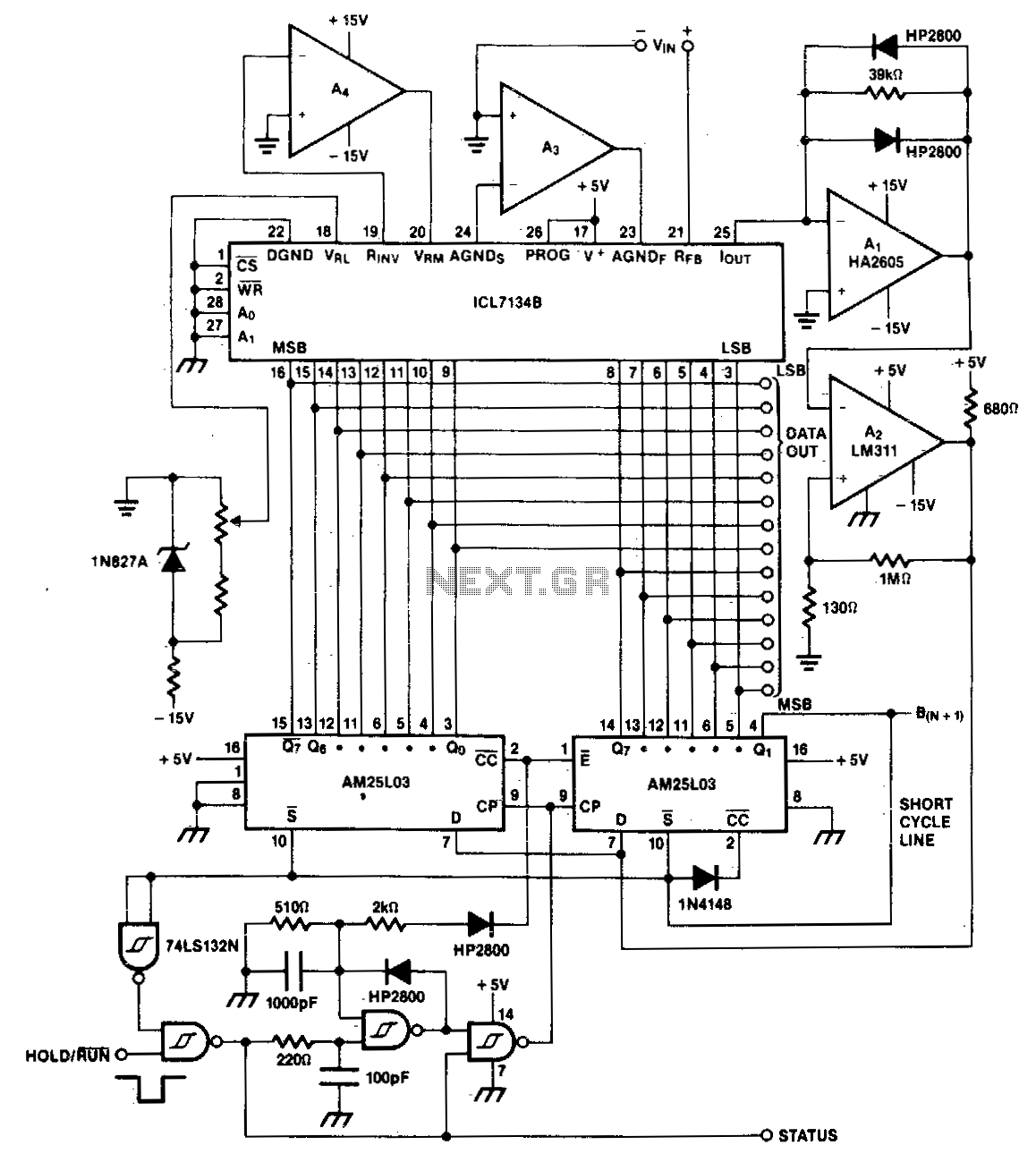
A bipolar input, high-speed A/D converter utilizes two AM25L03 devices to create a 14-bit successive approximation register. The comparator consists of a two-stage circuit featuring an HA2605 front-end amplifier, which is employed to minimize settling time issues at the...
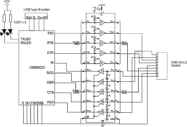
The FT8U232AM requires a small number of external components to produce a device that converts USB to TTL level RS232 signals. All that is needed is a TTL to RS232 converter to provide the 12V RS232 logic levels. The...
Before World War II the FM radio band was just below 50 Mc. Read all about it. If you have such a radio, you might want to build this converter. It will let your old set receive the modern...