
accurate reaction timer

The circuit design incorporates several key components to ensure accurate timing and functionality. The 555 timer ICs are critical in managing the timing sequences necessary for the reaction timer. The first 555 timer (IC1) is configured in monostable mode to generate a delay, the duration of which can be adjusted by the variable resistor (VR1). This flexibility allows the tester to customize the timing for different test scenarios.
The second 555 timer (IC2) serves as a trigger for the alarm system, providing auditory or visual feedback to the subject. The choice between the buzzer and LED alarm (controlled by switch S2) allows for adaptability depending on the testing environment. The brief activation period of 0.5 seconds ensures that the subject has sufficient time to respond without the alarm being overly intrusive.
The third 555 timer (IC3) is crucial for integrating the stopwatch functionality. It generates a pulse that briefly activates the Q2 transistor, which effectively simulates a press on the start/stop switch of the watch. This clever integration allows the watch to start counting automatically in response to the alarm, ensuring that the reaction time is accurately recorded.
The inclusion of the Q1 and Q2 transistors serves to isolate the 555 timer outputs from the watch circuit, preventing any potential damage from voltage spikes while maintaining reliable operation. The entire setup is designed to be user-friendly, allowing testers to easily initiate and monitor the reaction tests.
Overall, this reaction timer circuit is a versatile and effective tool for measuring human reflexes under various conditions, making it suitable for both casual testing and more structured experimental settings.Add a cheap stopwatch to this circuit to produce an accurate reaction timer. The circuit is wired in parallel with the start/stop button in the watch via a 2. 5mm socket, which fits snugly in one corner of the casing. The person conducting the test (the "tester") resets the stopwatch and turns on the reaction timer`s power switch (S3). The person b eing tested (the "subject") places his or her fingers near the "STOP" push-button switch (S4). Next, the tester covertly sets a delay time with VR1 and selects either the LED or buzzer alarm via S2. To initiate the sequence, the tester then presses the "START" switch (S1). This triggers 555 timer IC1, which is wired as a monostable. Its output (pin 3) goes high for 2-12 seconds as determined by the setting of VR1. At the end of this delay pin 3 goes low and triggers IC2, another 555 timer in monostable mode. The output from IC2 (pin 3) activates the alarm (buzzer or LED) for about 0. 5s. After inversion by Q1, it also triggers IC3, another 555 monostable. The positive pulse from IC3 turns on Q2, briefly closing the start/stop switch circuit in the watch. The watch starts to count up. After a short period, the subject reacts to the alarm and pushes the "STOP" button (S4), freezing the stopwatch.
The reaction time can then be read off with 1/100th of a second accuracy. Comparative reaction times could be measured when a subject is: rested or tired, silent or talking, before or after a night out, using a mobile phone, etc. For motoring realism, rig up dummy accelerator and brake pedals, with the brake switch making the stop contact.
Or take it to your club and test people as they enter and after they`ve been "steadying their nerves" at the bar. 🔗 External reference
Related Circuits
The foot 13 between valve value 1 and valve value 2 will draw the transistor base current. If the relay releases, after a recovery time of 0.5 seconds, pressing the key will initiate the switching process again. The timer...
A single hand clap will be picked up by the electric mic which is coupled through C1 into the op amp IC1. The output of IC1 triggers the 555 IC timer IC2 which is configured as a monostable multivibrator....
Q1 and Q2 create an ALL-ON ALL-OFF circuit that, when in the off state, draws negligible current. P1 initiates the circuit, activating the relay and powering the two integrated circuits (ICs). The lamp is energized through the relay switch,...
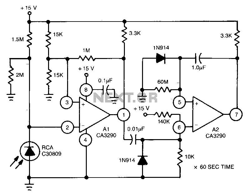
This circuit utilizes the CA3290 BiMOS dual voltage comparator to detect variations in the current of a light-emitting diode (LED). The output from the comparator triggers A2, a one-shot timer. If the light source to the photodiode is disrupted,...
The time is set by potentiometer R2, which provides a range from 1 second to 100 seconds, using a timing capacitor C1 of 100 µF. The output at pin 3 is normally low, keeping the relay in the off...
Utilizing the specified values depicted in the schematic diagram, this circuit features a timed ON period of 4 seconds. The ON time is governed by the values of capacitor C2 and resistor R3; increasing either C2 or R3 will...