
The VHF antenna switch

The circuit utilizes DIP-style RF relays that are sealed and RF shielded, ideal for applications in VHF frequency ranges. The relays are powered by a 12V supply and exhibit low contact capacitance, which is advantageous for minimizing signal loss. The design includes multiple antenna outputs, each capable of handling VHF signals, and allows for the simultaneous connection of multiple outputs through binary counting.
The RF relays are integrated into a switching mechanism that provides a user-friendly interface. An "instant set" button is included to facilitate quick selection of the VHF transmitter output, ensuring that the operator can quickly engage the necessary output without fumbling through multiple options. The inclusion of status-indicating LEDs provides immediate visual feedback, with a red LED indicating the active transmission state.
The circuit employs 7414 Schmidt trigger gates to debounce the switch inputs, which enhances reliability by preventing false triggering due to switch bounce. The capacitors connected to the gates ensure that the voltage transitions are smooth, further stabilizing the operation of the circuit. The design also incorporates a scanner output, which is strategically routed along the antenna to exploit ambient air capacitance, allowing for passive scanning of nearby signals without the need for active circuitry.
The enclosure of the circuit is designed to be completely sealed, enabling operation in harsh environments, including submersion in water. This robust design is complemented by the use of conductive rubber contacts, which offer a durable and reliable switching mechanism. The small PCB is securely mounted, ensuring that the conductive rubber maintains consistent contact with the etched contact points, promoting longevity and reliability in performance. Overall, this circuit represents a practical and innovative solution for RF relay applications in VHF communications.Finally I have found a use for a bunch of DIP-style RF relays I acquired in a grab-bag from a discount electronics shop some time ago. These babies are sealed totally, and rf shielded with low contact capacitance. Perfect for VHF frequencies. They are 12 volt and have a fairly decent coil resistance, although I wish they were latching style. I hav e several purchased antenna switches but they are all the same. Every few months they need to be pulled apart and cleaned as the contacts oxidize quickly. Perhaps there are better ones out there but frankly I`m sick and tired of looking by "buying and trying. " The solution of using relays isn`t without it`s draw backs, i. e. power consumption, but it`s minimal and can be turned into low draw mode by selecting no relay. As can be seen on the right side of the schematic, the 4 outputs are all VHF related. As the antenna will be 1/4 wave, SWR won`t be a problem and the EXT can be used for TV signals. This switch doesn`t just select single outputs but counts binarily through them all so 2 or more can be connected at the same time.
Caution must be used when using the VHF (2 meter) transmitter so one of the buttons has been designated as an "instant set" to that output only. ( D3 held high ) The LEDs being switched on with the realys show the status. Red alone must be on for transmitting. The 7414 gates are Schmidt triggers, famous for their ability to debounce switches. Once the zero crossing has occurred as button is pressed, it must be a certain voltage above that to flip back to it`s original state.
The caps are to ensure the slope is smooth. I intentionally place the trace for the scanner output along the antenna so it can "scan" off of the air capacitance without being actually turned on. ( This is just because I`m nosey! Also good for scanning vessels in close proximity ) A neat thing about this box is that it`s totally sealed.
I can submerse it in water and not leaks! As shown in this photo the switches are "stolen" conductive rubber contact style from a telephone. I went with round because they are easy to drill for. The small pc board is held on with tiny screws that compress the rubber to the aluminum. I just hand etched the contact "teeth" and it works fine! 🔗 External reference
Related Circuits
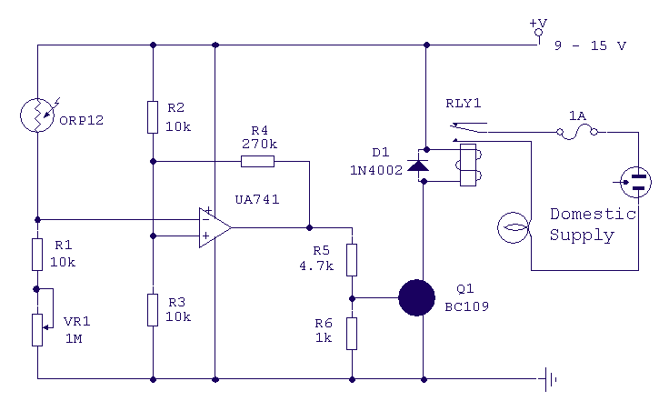
This circuit will activate a relay when light falls to a preset level. Light level can be adjusted with VR1 and the relay contacts may be used to operate an external light or buzzer. More: The light sensor used...

The diameter of the antenna elements can range from 5.8 mm, while the dipole diameter can vary from 8 mm to 12 mm, with 12 mm being the recommended size. This adjustment can be made without altering the length...
Operating high-beam headlights while driving on highways can significantly enhance visibility; however, it poses a blinding risk to other drivers. This straightforward circuit can be integrated into the headlight switch to facilitate automatic switching between high and low beam...

SI and S2 must be pressed within 200 ms of each other to activate K1. The hold time is adjustable via K7. Additionally, the overlap time of SI and S2 can be modified by changing C1 and C2 or...
It is noted that the LEDs are not configured in parallel with the transistor. If they were, the LEDs would illuminate when the transistor is off. Instead, the LEDs are connected in parallel before entering the transistor. The transistor...
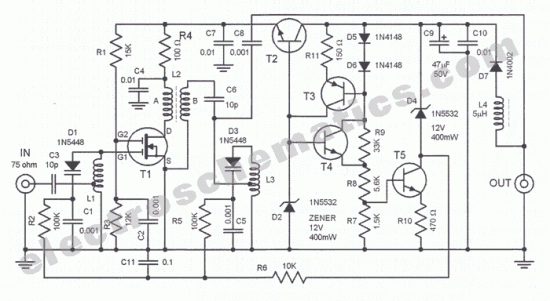
Utilize this FM antenna amplifier in locations where the reception of FM stations is poor. This circuit is specifically designed for this purpose. The FM antenna amplifier circuit is engineered to enhance signal strength for FM radio stations, particularly in...