
active balanced ground

The circuit design focuses on achieving a higher output voltage swing for the mono signal by carefully managing the gain and grounding. The schematic involves a differential amplifier configuration where the gain (G) is applied to the difference between two input signals, IL and IG, with respect to a reference ground (OG). This differential approach aims to minimize noise and enhance signal integrity. However, the design's effectiveness is contingent upon precise resistor matching to mitigate crosstalk, a common challenge in audio circuit designs.
The implementation has revealed several issues, particularly with grounding and signal cancellation. When all three channels are connected, the desired cancellation does not occur, indicating potential grounding problems or mismatched component values. Interestingly, disconnecting one side results in proper operation, suggesting that the design's grounding scheme requires further refinement.
The use of a TLE426 rail splitter is ideal for generating dual power rails, but the absence of this component led to the adoption of a generic op-amp splitter configuration. This substitution may contribute to the observed inconsistencies. The experimentation with various circuit configurations highlights the importance of thorough testing and validation, especially when transitioning from simulation to physical prototypes.
The suggestion to utilize a low-resistance potentiometer or a non-inverting op-amp as an input buffer is noteworthy, as these components can help stabilize the input signal and improve overall circuit performance. The connection method using alligator clips to the headphone jack is practical for prototyping, yet it may introduce additional variables affecting the circuit's behavior.
In summary, this circuit design aims for enhanced audio performance through careful gain management and grounding techniques. However, persistent issues with crosstalk and cancellation indicate the need for further investigation into component matching, grounding strategies, and circuit layout. A detailed schematic of the current setup would aid in diagnosing these issues and optimizing the design for better performance.Designed the same thing but for the reason of having a higher output voltage swing for the mono part of the signal. I personally don`t believe/understand Meier`s idea as voltages are just relative anyway aren`t they I haven`t read this entire thread but from what I can see is that your proposed method will have horrible cross talk unless you precisely match the resistors.
Here`s a schematic of how I was planning to do it. where G is the desired gain. It then puts the difference between IL and IG (the unnamed ground in the schematic) relative to OG multiplied by the gain. Similarly for the right channel. So you end up with. I tried it your way and it still doesn`t work. The results are pretty much the same as mine from before. if I disconnect one side, it works perfectly (ie: the ground signal cancels out what I don`t want to hear), but when I have all three it doesn`t.
If I only have OL and OR connected (no headphone ground), then I get almost full cancellation (because I can hear just a tiny bit of the original test tones which I will chalk up to improperly matched resistors). p. s. I did not have a TLE426 rail splitter, so I used the simple generic opamp splitter config shown halfway down the page here: Maybe I just have really junky parts, and I still think I have some weird grounding issue.
I dunno why, but my ground only works properly when I connect the input ground into the virtual ground. edit: Of note though. I have now attempted three variations on the circuit and all three have had the exact same problems. Since running these in simulation works properly, perhaps the theory is fine but maybe the culprit is something fishy on my end in terms of how I`m building the circuits (and if its an error somewhere, I sure am consistent!) I tried it your way and it still doesn`t work.
The results are pretty much the same as mine from before. if I disconnect one side, it works perfectly (ie: the ground signal cancels out what I don`t want to hear), but when I have all three it doesn`t. If I only have OL and OR connected (no headphone ground), then I get almost full cancellation (because I can hear just a tiny bit of the original test tones which I will chalk up to improperly matched resistors).
p. s. I did not have a TLE426 rail splitter, so I used the simple generic opamp splitter config shown halfway down the page here: No, I have not tried it, but plan to next time I`ve got a spare opamp. I`m going to read the whole thread now so I`ll see if I can spot any problems. That virtual ground should work fine. To use a pot you would need a very low resistance pot, like 100R, or use a non-inverting opamp as an input buffer, I think you have done the latter, correct To try and make sure you`ve wired it all up correctly, try and draw a schematic from what`s on your board ignoring what it is supposed to be then compare the two to check for any mistakes.
I would be interested if you could post a full schematic of the set up you`re using at the moment When I say connected it probably means to the headphone jack. I`m using alligator clips to connect the outputs directly to the tip/ring/sleeve of the headphone. Right now I`m just using an opamp as input buffer. I think it`s in inverting config right now, which shouldn`t matter as both left and right are inverted before feeding everything else so it should all work out in the end.
I`ve also skipped the input buffer and just wired directly into the circuit, but it doesn`t make a difference. I`ve gone over the circuits many times now. I`ve tried my method 1 and 2 listed on page two, and I`ve tried yours as well. My schematics on the board match what I have on paper as far as I can tell. I`m currently using dual channel opamps (so typically one opamps for the OG, and one opamp for both OL and OR).
I don`t have any single channel opamps, but I might try just using one side of each one to create my outputs. I will try to p 🔗 External reference
Related Circuits
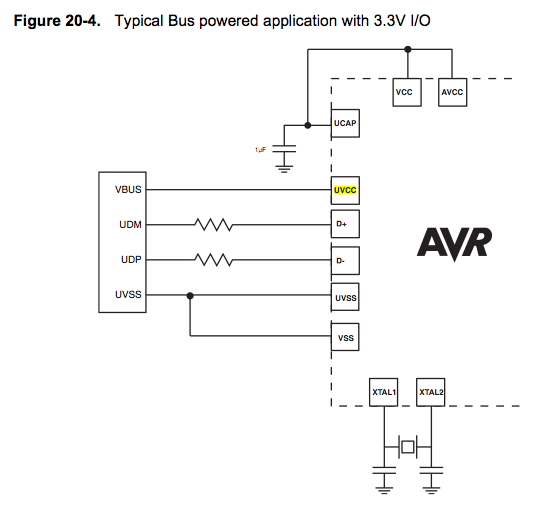
Since the microcontroller unit (MCU) is powered through USB, the common zero voltage should align with the supply voltage and thus be connected to the 0V (UVSS) line. In electronic circuit design, it is essential to ensure that the ground...

The Unmanned Ground Vehicle (UGV), also referred to as the Spycar project, is a radio-controlled four-wheeled platform capable of six different motions. This vehicle can be equipped with a wireless camera, allowing for video feedback to be transmitted to...
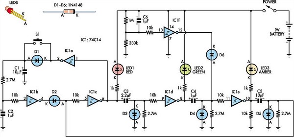
This toy traffic signal utilizes a single low-cost hex Schmitt-trigger inverter IC (IC1a-IC1f) to directly control three colored LEDs (red, green, and amber). Upon activation, the circuit illuminates the red signal for 30 seconds, followed by green for 6...
Electronics tutorial about active band-pass filters, including band-pass filter frequency response, its resonant frequency, and second-order response. Active band-pass filters are essential components in various electronic applications, particularly in signal processing, audio engineering, and communications. These filters are designed to...
After the 2-way active loudspeaker circuit, give a complete electronic section circuit of one 3-way active loudspeaker. The speaker's choice will become from you, because the particular circuit has the driving possibility of almost all trade loudspeakers. The choice...
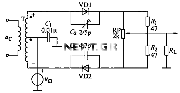
A common diode balanced modulator circuit is illustrated. It comprises two identical performance diodes and a center-tapped transformer configuration. The diodes used are VD1 and VD2, specifically 2AP9 models. The parameters for the circuit elements are detailed in FIG....