
Active Loudspeaker with Crossover II


Part List [Fig.1]
R1=47Kohms R19-20=47ohms C17-18=47uF 25V
R2=1Kohms C1=2.2uF 63V MKT TR1-2=47Kohms trimmer
R3=4.7Kohms C2=220pF IC1=TL071
R4-11-13-15-17=NC C3-4-11-12=100nF 63V MKT IC2-3=TL072-NE5532
R5-6=12Kohms C5-6-9-10=10nF 63V MKT J1=2pin conn. 2.54mm pin step
R7-8=120Kohms C13=6.8nF 63V MKT J2A=8pin conn. 2.54mm pin step
R9-10=220Kohms C14=3.3nF 63V MKT or 8 pinhead 2.54mm pin step*
R12-14=10Kohms C15=33nF 63V MKT
R6-18=33Kohms C16=18nF 63V MKT All Resistors are 1/4W 1%
Typical specifications
Input sensitivity: 1Vrms
Input impedance: 47K
High Pass filter: 20Hz - 200Hz
Band Pass filter: 200Hz - 3500Hz
Low Pass filter: 3500Hz - 20kHz
Slope: -12dB/oct
This 3-way active loudspeaker circuit is designed to provide a versatile and high-fidelity audio experience. The circuit utilizes a Butterworth crossover topology, ensuring a smooth frequency response with minimal phase distortion. The choice of cutoff frequencies at 200Hz and 3500Hz allows for optimal separation of audio signals across three distinct frequency bands: low, mid, and high.
The input stage of the circuit features a sensitivity of 1Vrms, accommodating a wide range of audio sources. The input impedance of 47Kohms ensures compatibility with various audio devices, minimizing signal loss.
The high-pass filter operates between 20Hz and 200Hz, effectively removing unwanted low-frequency noise and allowing only higher frequencies to pass to the mid-range speaker. The band-pass filter, spanning 200Hz to 3500Hz, processes the mid frequencies, ensuring clarity and detail in vocal and instrumental sounds. Finally, the low-pass filter operates from 3500Hz to 20kHz, delivering crisp high frequencies to the tweeter while preventing distortion from lower frequency signals.
The circuit also includes adjustable trimmers (TR1 and TR2) for fine-tuning the output levels of the high and mid speakers, providing flexibility in balancing the sound profile according to the user's preferences or room acoustics.
The PCB design facilitates easy integration of the crossover circuit, allowing for modular upgrades or adjustments. The use of standard component values is emphasized to ensure consistency and reliability across different builds, with recommendations for combinations of resistors and capacitors to achieve desired specifications when standard values are unavailable.
Overall, this 3-way active loudspeaker circuit is engineered for high performance, adaptability, and ease of use, making it suitable for both professional and home audio applications.After the 2-way active loudspeaker circuit, give a complete electronic section circuit of one 3-way active loudspeaker. The speaker?s choice will become from you, because the particular circuit has the driving possibility all almost trade loudspeakers.
The choice that made in the crossover stage, is a 3-way crossover [Butterworth] with cut off -point frequencies 200HZ and 3500HZ, with slope -12dB/oct. These frequencies can change and adapted in your own speaker?s choice, using the calculation types of Fig.5.
Exist the possibility is used other circuit crossover, as the circuit of 3-way active crossover with slope -24dB/oct. The circuit crossover does not exist above in main PCB, but is contact with this via the plug J2A that is applied above in the J2B.
This can become if in the place of J2A it?s placed a pinhead with 8 pin and PCB crossover put on above main PCB in form sandwich. It can however be placed in other point and with a flat cable to transport the signals and the voltages from J2A in the J2B.
Power supply for ± 15V of the crossover circuits it?s found in main PCB. A point that I want to highlight is with regard to various in the calculation values precision and real values of resistors and capacitors. It?s good, if the component value does not exist in standard value to select a combination that us will give value near in theoretical and simultaneously to do the same and in the other loudspeaker, in order that the divergence is same.
In the drawing exist parallel combinations resistors, and somebody?s from these are not used if they do not need. With the TR1-2 we adjust the level of high and mid speakers, if it needs. Part List [Fig.1] R1=47Kohms R19-20=47ohms C17-18=47uF 25V R2=1Kohms C1=2.2uF 63V MKT TR1-2=47Kohms trimmer R3=4.7Kohms C2=220pF IC1=TL071 R4-11-13-15-17=NC C3-4-11-12=100nF 63V MKT IC2-3=TL072-NE5532 R5-6=12Kohms C5-6-9-10=10nF 63V MKT J1=2pin conn.
2.54mm pin step R7-8=120Kohms C13=6.8nF 63V MKT J2A=8pin conn. 2.54mm pin step R9-10=220Kohms C14=3.3nF 63V MKT or 8 pinhead 2.54mm pin step* R12-14=10Kohms C15=33nF 63V MKT R6-18=33Kohms C16=18nF 63V MKT All Resistors is 1/4W 1% Typical specifications Input sensitivity 1Vrms Input impedance 47K High Pass filter 20HZ-:-200HZ Band Pass filter 200HZ-:-3500HZ Low Pass filter 3500HZ-:-20KHZ Slope -12dB/oct 🔗 External reference
Related Circuits
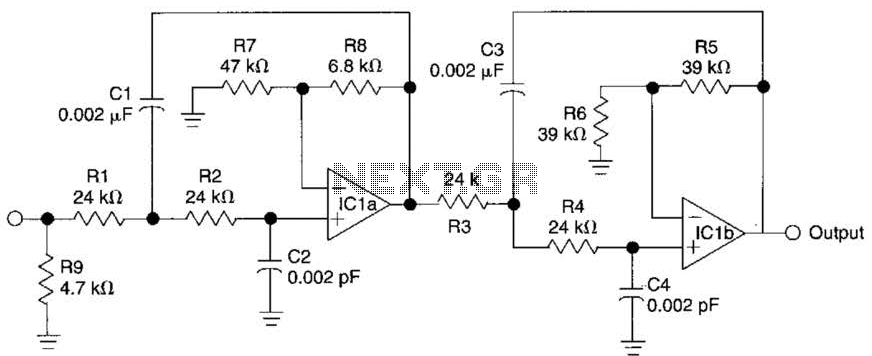
This circuit is a fourth-order low-pass filter designed for operation at kilohertz frequencies. The component values for resistors R1, R2, and capacitors C1, C2, as well as resistors R3, R4 and capacitors C3, C4 can be adjusted for functionality...
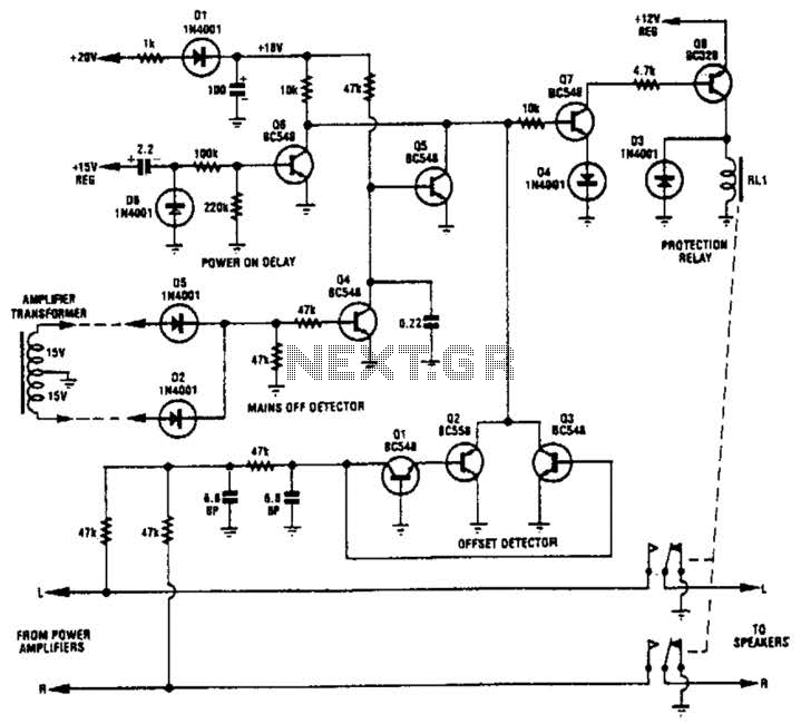
Transistors Q1, Q2, and Q3 monitor the two outputs of the stereo amplifier. If the offsets exceed 2 V, Q7 is turned off, which in turn deactivates Q8 and the normally on relay. Diodes D2 and D5, along with...
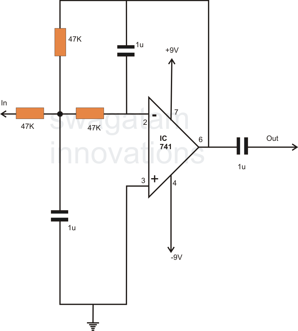
In electronics, filter circuits are primarily used to restrict the passage of certain frequency ranges while allowing other frequency bands to proceed to subsequent stages of the circuit. A high-pass filter circuit permits only frequencies that exceed a specified...
Unique applications of the 567 tone/frequency decoder IC include a pulse generator with a 25% duty cycle (active factor). This signal generator produces a specific output. The 567 tone/frequency decoder IC is a versatile component widely utilized in various electronic...
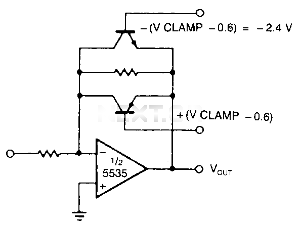
The modified inverting amplifier employs an active clamp to precisely limit the output swing. Consideration must be given to the VBE of the transistors. The output swing is restricted by the base-emitter breakdown of the transistors. A straightforward circuit...
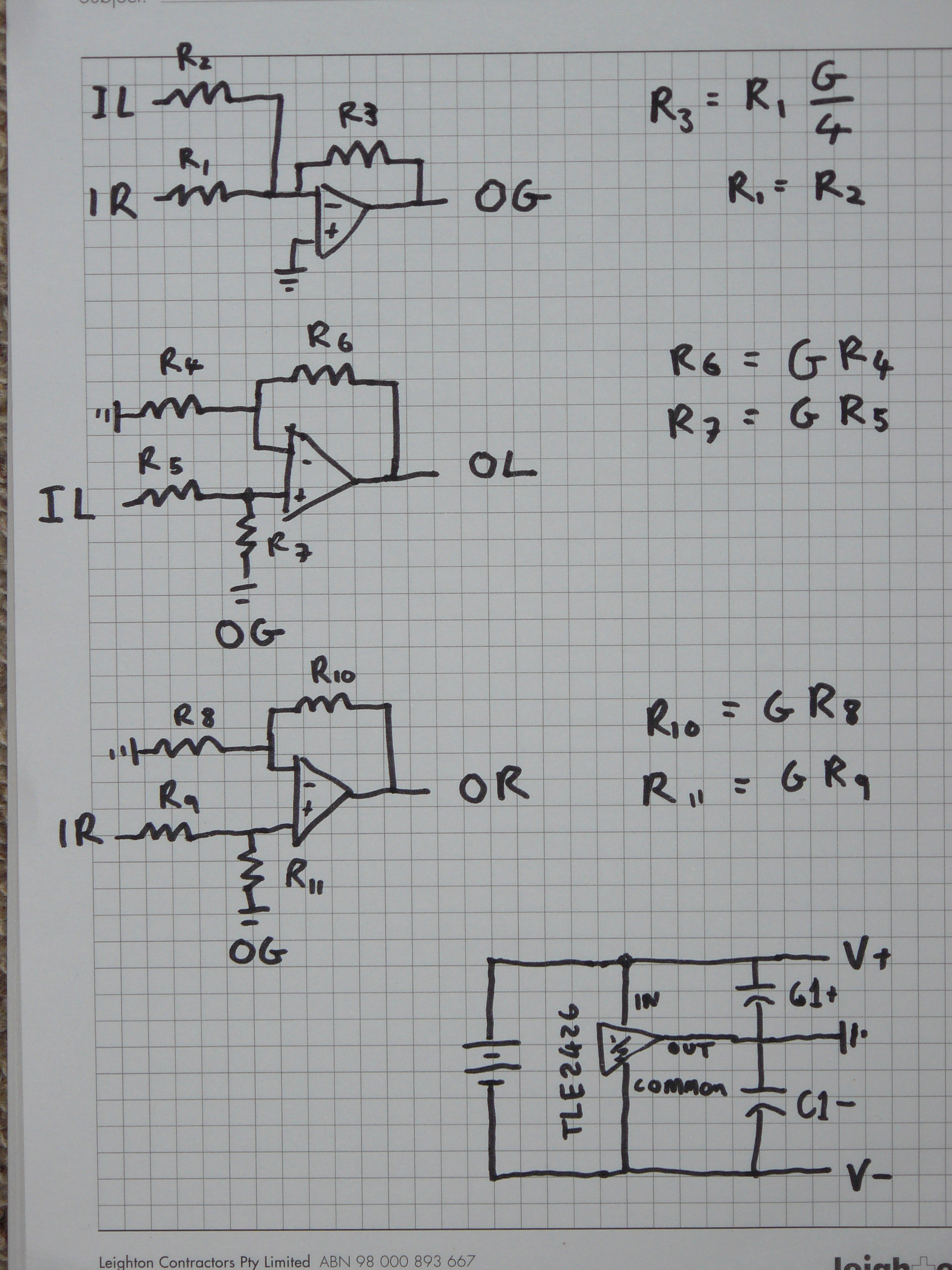
The design aims for a higher output voltage swing for the mono part of the signal. There is skepticism regarding the proposed method due to potential crosstalk issues unless resistors are precisely matched. A schematic was planned where G...