
Active Crossover Circuit-Schematic-Design and Diagram

The active crossover circuit is an essential component in high-fidelity audio systems, allowing for the separation of audio signals into different frequency bands before amplification. This particular design focuses on a 2-way crossover configuration utilizing the LM833 operational amplifier, known for its low noise and high performance characteristics, which enhance audio quality.
In this circuit, the input audio signal is split into two frequency ranges: the low-frequency signals are directed to a subwoofer or woofer, while the high-frequency signals are sent to a tweeter. The crossover point, typically adjustable, determines the frequency at which the audio signal is divided.
The schematic includes two main sections: the low-pass filter and the high-pass filter. The low-pass filter allows frequencies below the crossover point to pass through while attenuating higher frequencies. Conversely, the high-pass filter permits frequencies above the crossover point to pass while blocking lower frequencies.
Components in the circuit include resistors and capacitors that define the filter characteristics, as well as the LM833 op-amps that provide the necessary gain and buffering for the signals. The design can be implemented on a PCB or a breadboard for prototyping, allowing for adjustments and fine-tuning of the crossover frequency and filter slope.
For optimal performance, careful attention should be paid to component selection, layout, and grounding to minimize noise and interference. This active crossover circuit is ideal for DIY enthusiasts looking to enhance their audio systems with precise control over frequency distribution, resulting in improved sound clarity and overall listening experience.Active crossover circuit design,circuit diagram,schematic, diy active crossover circuit,HiFi audio crossover, 2 (band) way crossover circuit using LM833.. 🔗 External reference
Related Circuits
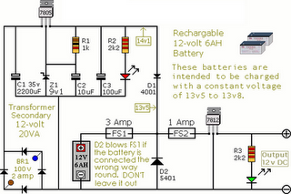
The following circuit illustrates an Alarm Power Supply Circuit Diagram. Features include a 1-amp current output, suitable for a Modular Burglar Alarm operating at 12 volts. The Alarm Power Supply Circuit is designed to provide a stable and reliable power...
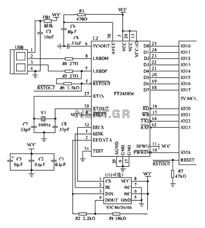
The FT245BM typical hardware circuit operates in bus-powered mode and employs a power-on reset mechanism to initialize the device. The clock circuit can be implemented using a 6 MHz crystal oscillator module or a combination of a 6 MHz...
The crossover network is designed for extending an existing audio installation by adding a subwoofer. Often, this subwoofer is a previously unused unit. If its frequency response is adequate, it requires a filter to eliminate any frequencies above approximately...

The circuit illustrated in the figure involves the MAX6698 maximum temperature sensor, which utilizes three transistors (VT1 to VT3) and three thermistors (RT1 to RT3). An internal reference voltage source is connected through resistors UREF REX1 to REX3, providing...
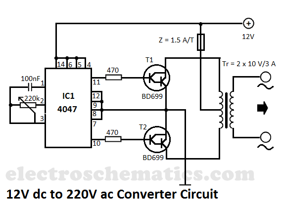
This DIY 12V to 220V voltage converter is built with the CMOS 4047, which serves as the main component of this compact voltage converter that transforms 12V DC into 220V AC. The 4047 is configured as an astable multivibrator,...

Laptop schematic diagram featuring DDR1 and DDR2 memory slots, a mobile CPU with a 478 Celeron architecture, an ICH7M chipset, an audio circuit utilizing the G1431Q component, a Codec ALC268, an operational amplifier G1412, a modem MDC card, integrated...