
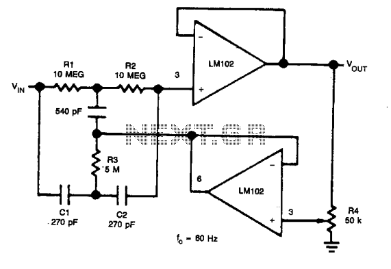
Active low-pass filter LM102 schematic

The active low-pass filter circuit is designed to attenuate frequencies above the cut-off frequency while allowing lower frequencies to pass through with minimal attenuation. The cut-off frequency, defined by the formula fc = 1/(2πRC), is determined by the values of the resistors and capacitors used in the circuit. In this case, the chosen cut-off frequency of 10 kHz indicates the point at which the output signal begins to decrease in amplitude relative to the input signal.
When configuring the circuit, the selection of resistor and capacitor values is crucial. For instance, if R1 is set equal to R2, it maintains a balanced voltage divider, which is essential for stable operation. The relationship between C1 and C2, where C1 is double the capacitance of C2, allows for flexibility in tuning the filter's response characteristics. This configuration can be particularly useful in applications where precise filtering is required, such as in audio processing or signal conditioning.
Alternatively, setting C1 equal to C2 and R1 equal to twice R2 creates a different filter response, which can be useful in scenarios where a specific phase shift or gain is desired. The ability to adjust these parameters provides versatility in designing filters tailored to specific frequency responses or application requirements.
Overall, the active low-pass filter circuit is a fundamental building block in electronic design, providing essential functionality in a wide range of applications, from audio systems to data acquisition and signal processing. Careful consideration of component values and configurations will yield optimal performance in filtering unwanted high-frequency noise while preserving the integrity of the desired low-frequency signals.Shown for the active low pass filter circuit. Cut-off frequency fc of the circuit = 10kHz. Circuit, R1 and R2 ratio and the ratio of C1 and C2 can be various values. This circuit uses R1 = R2 and C1 = 2C2. Using C1 = C2 and R1 = 2R2 can.
Related Circuits
This circuit is designed to indicate when room noise exceeds a predetermined threshold, utilizing a flashing LED to signal this condition. Three fixed noise levels are selectable: 50 dB, 70 dB, and 85 dB. The circuit employs two operational...
This digital DIY tachometer for bicycles utilizes two reed switches to gather speed information. The reed switches are positioned near the wheel rim, where permanent magnets, attached to the wheel spokes, pass by and activate the switches. The speed...
In applications where the rejected signal may slightly deviate from the null point in a notch network, it is beneficial to decrease the Q factor of the network. This adjustment ensures consistent rejection across a broader range of input...
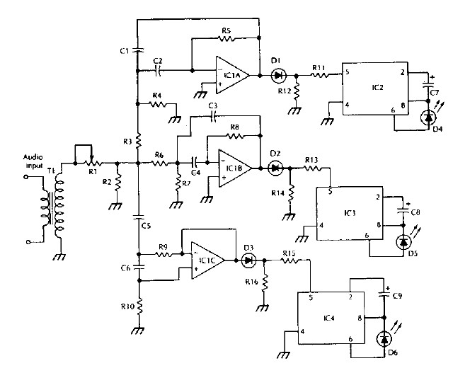
The LM 3909 LED flasher integrated circuit (IC) can be utilized to design various electronic projects. A circuit diagram illustrates the creation of a simple color organ using the LM3909 LED flasher IC. Three active filters process the audio...

An electronic rectification circuit that avoids the use of large, heavy, and expensive electrolytic capacitors by utilizing an active transistor in a gyrator configuration. To minimize excess ripple output on a power supply feeding a heavy load, a large...
It includes a starter for each lamp that heats the filaments (cathodes) at both ends of the lamp before ignition. Once the lamp is lit, the heated filaments are no longer necessary. The heating serves solely as an ignition...