
active medium wave antenna

The circuit effectively enhances the performance of a telescopic whip antenna by utilizing a preamplifier tailored for medium wave reception. The design incorporates a 10k potentiometer (RV2) for tuning voltage, which is essential for adjusting the sensitivity of the antenna to incoming signals. The dual-gate MOSFET (TR1) plays a critical role in signal amplification, allowing for precise control over the gain through the application of a control voltage to its gates.
The use of a 330 µH coil in conjunction with KV1235 varicap diodes ensures that the antenna maintains high selectivity, enabling it to filter out unwanted signals and focus on the desired frequency range. The BF981 MOSFET serves as a key component in maintaining the stability and performance of the circuit, supported by a 6.2V zener diode that provides a stable power supply to the MOSFET stage.
The composite amplifier configuration formed by the two BC548 transistors (Q2 and Q3) enhances the output stage, ensuring that the low impedance requirements of 50 ohm receivers are met. Q2's common emitter configuration boosts the voltage gain, while Q3's emitter follower setup minimizes output impedance, resulting in an efficient signal transfer to the receiver.
Furthermore, the design's adaptability for other frequency bands by changing the coil value or using a relay switch allows for versatility in applications, making it suitable for various medium waveband scenarios. Overall, this circuit diagram presents a sophisticated approach to improving the input capabilities of telescopic whip antennas, ensuring high performance and flexibility in signal reception.Circuit diagram is designed to strengthen the input of a telescopic whip antenna. The Preamplifier is designed to cover the medium waveband from about 550Khz to 1650Khz. Tuning voltage is supplied via RV2, a 10k potentiometer connected to the 12 Volt power supply. RV1 is controlled so that the amplified signal is weak or strong signal will be atte nuated. Control voltage applied to gate 2 of TR1, a dual-gate MOSFET, a voltage signal via gate 1; signal into multiple inputs are set through a 330uH coil and two MOSFETs KV1235 varicap diodes on inputs and by the same component in the BF981 MOSFET`s drain terminal. Both tuned circuits provide high selectivity in the entire tuning range. To help the stability of the MOSFET stage is fed from a 6. 2V zener supply stable. The following is a schematic drawing: To drive low impedance (50 ohms) receiver, the output impedance of the medium stage is enhanced by the BF981 is made of a composite amplifier Q2 BC548 and Q3 BC548.
Q2 operating in Common emitter voltages increase by more than just 2, operates in emitter follower Q3 is to provide a circuit with low output impedance. Finally, this active antenna can be used in other bands by changing the values of the 330uH coil. To perform in some bands or relay switch can be used to change the value of the coil. 🔗 External reference
Related Circuits
When an alternating current signal is applied to a capacitor, the phase of the charging current and the voltage across the capacitor shifts by 90 degrees. Conversely, when an alternating current signal is applied to an inductor, the voltage...

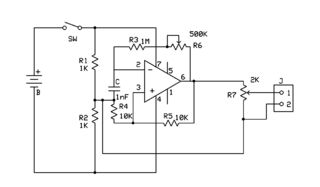
A simple active mixer is desired to be placed in front of a power amplifier. Research has been conducted on active operational amplifier (op-amp) mixers, which provide various insights. An active mixer utilizing operational amplifiers (op-amps) is an essential circuit...
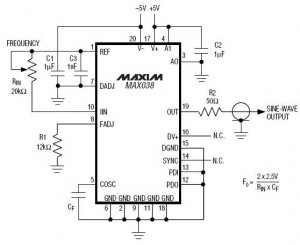
A high-frequency waveform generator is highly beneficial for electronic experimentation and design. This circuit generates sine wave oscillations; however, it can be modified to produce triangle or square wave functions. The frequency can be controlled using current. By disconnecting...
An attempt has been made to follow an instructable for some time; however, understanding its schematic remains challenging. The issue is not a lack of knowledge regarding the symbols used. In electronic schematics, symbols represent various components and their connections...
The circuit was designed to create a portable and sensitive regenerative receiver suitable for shortwave band listening. The regenerative receiver circuit is engineered to operate effectively within the shortwave (SW) frequency range, which typically spans from 3 MHz to 30...

An audio filter is positioned at the input of each audio integrated circuit (IC) chip to filter the audio signal intended for speakers. A low-pass filter is utilized for the woofer, while a high-pass filter is employed for midrange...