
High Selective Regenerative Shortwave Receiver

The regenerative receiver circuit is engineered to operate effectively within the shortwave (SW) frequency range, which typically spans from 3 MHz to 30 MHz. This design utilizes a feedback mechanism to enhance sensitivity and selectivity, making it particularly adept at picking up weak signals that are characteristic of shortwave broadcasting.
Key components of the circuit include an RF amplifier stage, a regenerative detector, and an audio output stage. The RF amplifier is crucial for boosting incoming radio frequency signals, while the regenerative detector converts these signals into audio frequencies. The feedback loop in the regenerative stage is carefully tuned to optimize gain without introducing excessive distortion, allowing for clear audio reproduction.
The circuit's portability is achieved through the use of low-power components, enabling it to be powered by batteries. This makes it suitable for outdoor use or in locations where access to power sources is limited. Additionally, the design may incorporate a compact tuning mechanism, such as a variable capacitor, to allow users to easily adjust the frequency and lock onto desired stations.
Overall, this regenerative receiver circuit is an excellent choice for enthusiasts of shortwave listening, providing a balance of sensitivity, portability, and ease of use.The circuit was designed to create a portable and sensitive regenerative receiver that will be suitable for shortwave band listening. Shortwave (SW) a t.. 🔗 External reference
Related Circuits

This design features a simple yet effective receiver with good sensitivity and selectivity. The circuit utilizes a compact three-transistor regenerative receiver with fixed feedback, primarily based on the BC549 transistor. The tuned circuit is intended for medium wave frequencies...
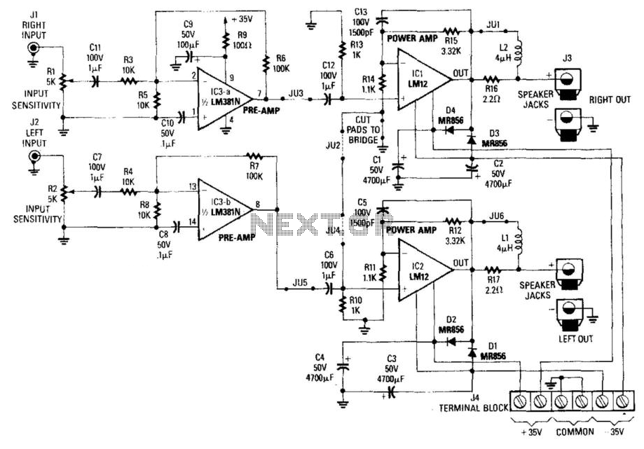
Note for bridge configuration: 1. Install jumpers JU2 and JU4. 2. Remove J1. 3. Remove RIO. 4. Replace R13 with a jumper wire. 5. Replace R15 with a 4.53 kΩ, 1% resistor. 6. Replace R14 with a 13 kΩ,...
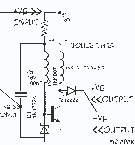
This circuit diagram is provided for those interested. It is a small circuit that takes an input of 1.5 volts and outputs 120 volts. The circuit in question is a voltage step-up converter, commonly referred to as a boost converter....
A function generator that operates within a frequency range of 0.1 Hz to 20 MHz can be easily constructed using the MAX038 integrated circuit chip. This describes a straightforward implementation of the device. The MAX038 is a precision waveform generator...
This high voltage converter circuit operates from a 30-volt power supply and can output a voltage ranging from 0 to 3 kV in version 1 or from 0 to 10 kV in version 2. The high voltage converter circuit is...
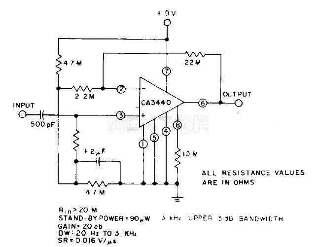
This circuit utilizes the low power leakage, high input impedance, frequency response, and capacitance characteristics of the CA3440 operational amplifier. Only one input coupling capacitor of 500 pF is required to attain a -3 dB low frequency response at...