
Battery Test Circuit Circuit

The circuit employs a voltage comparator to monitor the input voltage and determine its level. The reference voltages for low and high thresholds can be set using a voltage divider network, which typically consists of resistors. For the low voltage threshold (11 V), the circuit can be designed using an operational amplifier configured as a comparator. When the input voltage drops below this threshold, the output of the comparator switches, turning the LED on steadily to indicate a low voltage condition.
In the normal voltage range (11 to 15 V), the comparator output remains low, keeping the LED off. To detect the high voltage condition (greater than 15 V), a second comparator can be implemented. This comparator would be configured to activate when the input voltage exceeds the high threshold. Upon activation, a timer circuit, such as a 555 timer in astable mode, can be integrated to cause the LED to blink at a frequency of 1 Hz, providing a visual indication of the high voltage status.
The circuit's design ensures that it can handle a range of input voltages while providing clear visual feedback through the LED. Additionally, the use of appropriate resistors and capacitors will stabilize the circuit operation and prevent false triggering due to transient voltage spikes. This voltage level indicator circuit serves as a critical tool in monitoring electrical systems, ensuring they operate within safe voltage ranges, and alerting users to potential issues before they escalate. Using this circuit, tiiree levels of voltage can be displayednormal (11 to 15 V), liigh (>15 V), and low (11 V). When the voltage is low, the LED glows steadily. In the normal range, the LED is off. When the voltage is high, the LED blinks at a 1-Hz rate. This circuit is useful for assuring proper electrical system operation.
Related Circuits
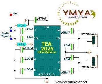
This is a simple portable audio amplifier circuit. The circuit is built around the TEA2025 integrated circuit, which is a monolithic audio amplifier housed in a 16-pin dual in-line package manufactured by UTC. The circuit features an internal thermal...
The DTMF codec stands for dual-tone multi-frequency codec. The multiple-channel infrared remote control switch circuit that incorporates the DTMF is depicted in the figure. It consists of an infrared remote control signal emitter, an infrared receiving signal amplifier, a...
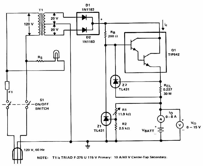
Lead Acid Battery Charger with current limit power supply. Refer to the specified page for an explanation of the related circuit diagram. The lead-acid battery charger with a current limit power supply is designed to safely charge lead-acid batteries while...
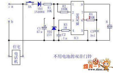
Utilize the 48V (60V) DC feedback electric current supplied by the phone feedback line as the operational energy source for the electronic doorbell, which is highly economical and practical. This document introduces a two-tone doorbell circuit that operates without...
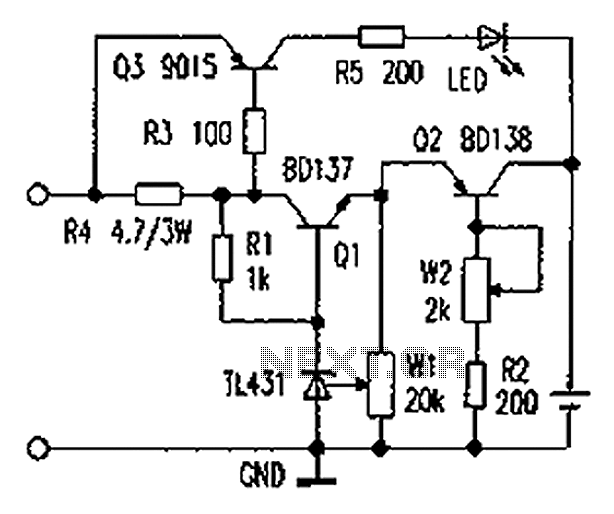
As illustrated in the figure, the lithium battery charging control board employs a constant current charging mechanism. The components Q1, R1, W1, and TL431 form a precision adjustable voltage regulator circuit. The components Q2, W2, and R2 create an...
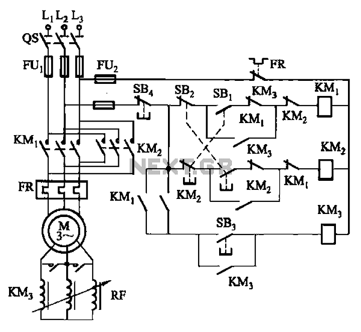
The circuit illustrated in Figure 3-166 employs a button control mechanism. To initiate forward motion, the user presses button SB1, which activates the motor rotor through a frequency-sensitive rheostat (RF). As the motor speed approaches its rated speed, a...