
DC Protection Time Delay for Loudspeaker circuit

The circuit design incorporates a relay (RL1) that serves as a switch for controlling the power supply to the amplifier. When the circuit is powered on, a timing mechanism initiates a one-second delay before RL1 closes, allowing the power supply capacitors to charge without introducing audible noise to the headphone output. This delay is critical in ensuring that transient noises do not interfere with the listening experience.
The resistor Rx is strategically placed to help manage the timing characteristics of the relay, ensuring that the delay is consistent and reliable. The choice of resistor value can be adjusted based on the specific requirements of the circuit, such as the charging time of the capacitors and the desired delay duration.
Simultaneously, the circuit includes a monitoring system that checks for the presence of DC voltage at the output of the amplifiers. This feature is essential for protecting the headphones and loudspeakers from potential damage caused by DC signals. If the monitoring system detects that the output is free of DC voltage, the relay activates, allowing the amplifiers to connect to the loudspeakers.
Overall, this circuit design effectively combines delay management and output monitoring to enhance the performance and reliability of audio amplification systems. The careful integration of components ensures that users experience a high-quality audio output without unwanted noise or distortion during startup.The particular circuit combines enough operations, as Smooth departure of benefit of AC line of network, with delay 1sec, to the transformers of power supply of amplifier, via the RL1 and the resistance Rx. (see block diagram). [ 2 ] Delay of connection of expenses of final amplifiers, in headphone, in order that noises emanating from the charge - uncharged of capacitors of power supply, they do not pass in them.
Simultaneously becomes control of exit of amplifiers for existence of continuous voltage [DC]. If all go well it connects, the amplifiers in loudspeaker.. 🔗 External reference
Related Circuits
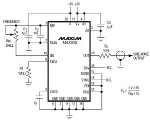
A high-frequency waveform generator is highly beneficial for electronic experimentation and design. This circuit generates sine wave oscillations; however, it can be modified to produce triangle or square wave functions. The frequency can be controlled using current. By disconnecting...
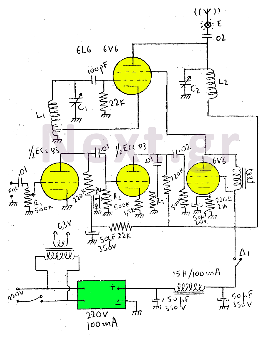
This circuit features a wearer assembly that includes a single lamp, either a 6V6 or 6L6, functioning as both an oscillator and an output amplifier. Coil L1 serves as the medium wave oscillation coil, while coil L2 is composed...
This scheme is a Standing Wave Ratio (SWR) meter, which is relatively simple and can be easily constructed. Once a directional coupler is created, the results will be indicated on the measuring LED meters as a ratio of SWR. The...
The circuit operates correctly on a breadboard, with the LED blinking at a frequency of 2 Hz. However, when soldered onto a perfboard, the LED blinks at a significantly higher frequency, approximately 10 Hz, although this is an estimation...
This circuit is appropriate for any scenario where over-current protection is necessary. An example from the model train hobbyist community illustrates its importance. Experienced model train enthusiasts understand that locating the source of a short circuit can be quite...
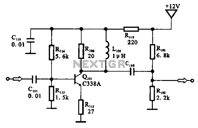
The amplifier circuit is designed as a pre-amplifier configuration. It utilizes transistor Q101 and other components such as inductor L101 and biasing elements. The transistor operates as a common emitter intermediate frequency (IF) amplifier. The IF signal is coupled...