
Adjustable half-wave rectifier charging circuit

The adjustment potentiometer, designated as RP, serves a critical function in regulating the charging current within an electronic circuit. This component is typically a variable resistor that allows for fine-tuning of the current flowing into a battery or capacitor during the charging process. By adjusting the resistance value, the user can effectively control the amount of current that passes through the circuit, which is essential for optimizing charging efficiency and prolonging the lifespan of the energy storage device.
In practical applications, the potentiometer is integrated into the circuit in such a way that it can be accessed easily for adjustments. It may be connected in series with the charging path to ensure that any changes made to the resistance directly influence the charging current. The adjustment can be made manually through a dial or screw mechanism, allowing for real-time changes based on the requirements of the specific application.
Moreover, the use of an adjustment potentiometer is particularly beneficial in circuits where varying load conditions may necessitate different charging rates. For instance, in solar charging applications, the amount of sunlight can fluctuate, affecting the optimal charging current. The ability to adjust the charging current dynamically helps to ensure that the energy storage device is charged efficiently and safely, preventing overcharging or undercharging scenarios.
In summary, the adjustment potentiometer RP is an essential component for controlling charging currents, enhancing the performance and reliability of electronic systems that rely on batteries or capacitors for energy storage. Its role in fine-tuning the current flow is vital for achieving the desired operational characteristics of the circuit.Adjustment potentiometer RP, can change the charging current.
Related Circuits
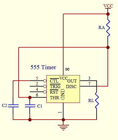
The timer circuit is utilized in various projects and is primarily categorized into two types. The first type is an analog RC circuit, where the charging of the capacitor determines the timing of the circuit. This type has a...
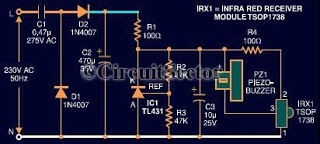
This document presents an infrared remote control tester circuit that can be constructed at a low cost. The circuit is built around the infrared receiver module TSOP1738. The state of the remote control can be observed through the sound...
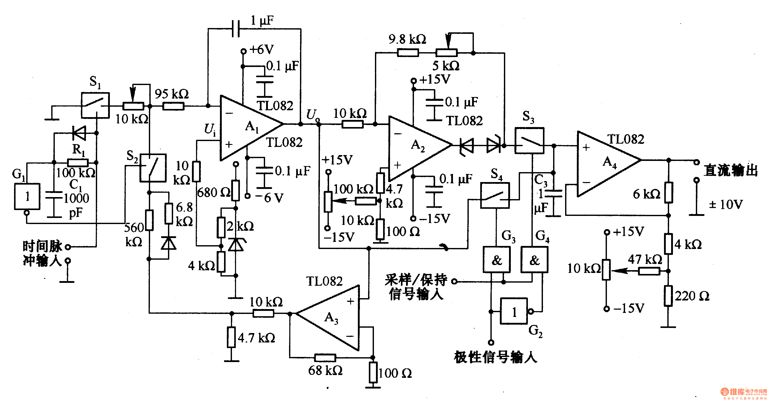
This circuit is designed for pulse width (time) to voltage conversion. According to the component parameters in the diagram, it can convert a pulse width of 0.1 seconds into an output voltage of 10V. When a conversion pulse is...
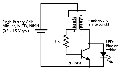
This circuit is commonly referred to as a Joule Thief, and it has been frequently encountered in various electronics videos on YouTube. The Joule Thief is a simple, low-cost circuit designed to extract energy from a single-cell battery, particularly when...
A newer version of this circuit board is available. Rev 4 includes a faster CPU, more memory, more I/O, and an optional LCD. It is recommended to use Rev 4 for new projects. Although the older board is no...
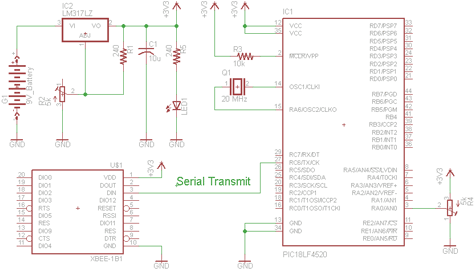
There are two schematics to examine for constructing a transmitter/receiver system. The first schematic is the transmitter, featuring a variable trimpot connected to RA0. The trimpot's value will be transmitted from the Tx pin of the PIC to the...