
joule thief circuit power a white blue led from a 1 5v battery

The Joule Thief is a simple, low-cost circuit designed to extract energy from a single-cell battery, particularly when the battery voltage is too low to power conventional devices. It operates using a self-oscillating boost converter topology, which allows it to convert the low voltage of a depleted battery into a higher voltage sufficient to drive an LED or other low-power devices.
The primary components of a Joule Thief circuit include a transistor (usually a bipolar junction transistor), a resistor, a toroidal inductor or transformer, and a light-emitting diode (LED). The circuit typically operates with a 1.5V battery, such as an AA or AAA cell, but can also work with other low-voltage sources.
In operation, when the circuit is powered, the transistor is turned on, allowing current to flow through the inductor, which stores energy in its magnetic field. Once the current reaches a certain level, the transistor turns off, causing the magnetic field to collapse. This collapse induces a voltage spike in the inductor, which can be several times higher than the input voltage. This induced voltage is then used to power the LED.
The resistor in the circuit serves to limit the base current to the transistor, ensuring that it operates within safe parameters. The choice of inductor and its inductance value is crucial, as it affects the frequency of oscillation and the efficiency of energy transfer.
Overall, the Joule Thief is an excellent example of how simple electronic components can be utilized to maximize energy efficiency, making it a popular project for hobbyists and educators in the field of electronics.I`ve seen this circuit around before, but it kept cropping up while looking at other electronics videos on YouTube. It`s called a Joule Thief, and it was.. 🔗 External reference
Related Circuits
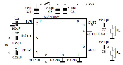
The car radio application utilizes a Class AB Audio Power Amplifier, typically featuring the TDA7360 IC. This amplifier provides 22W output in either bridge or stereo configuration and includes several beneficial features such as a minimal requirement for external...
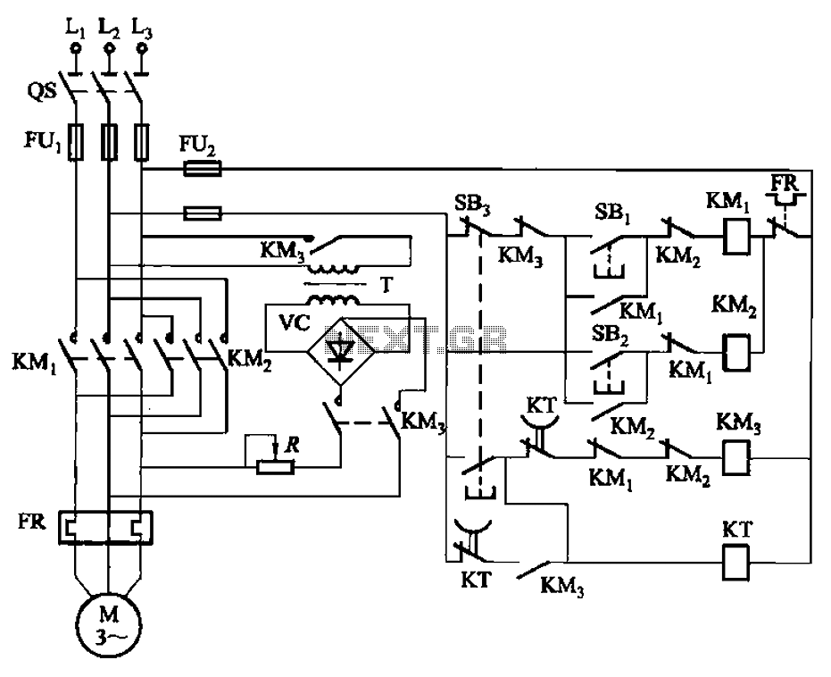
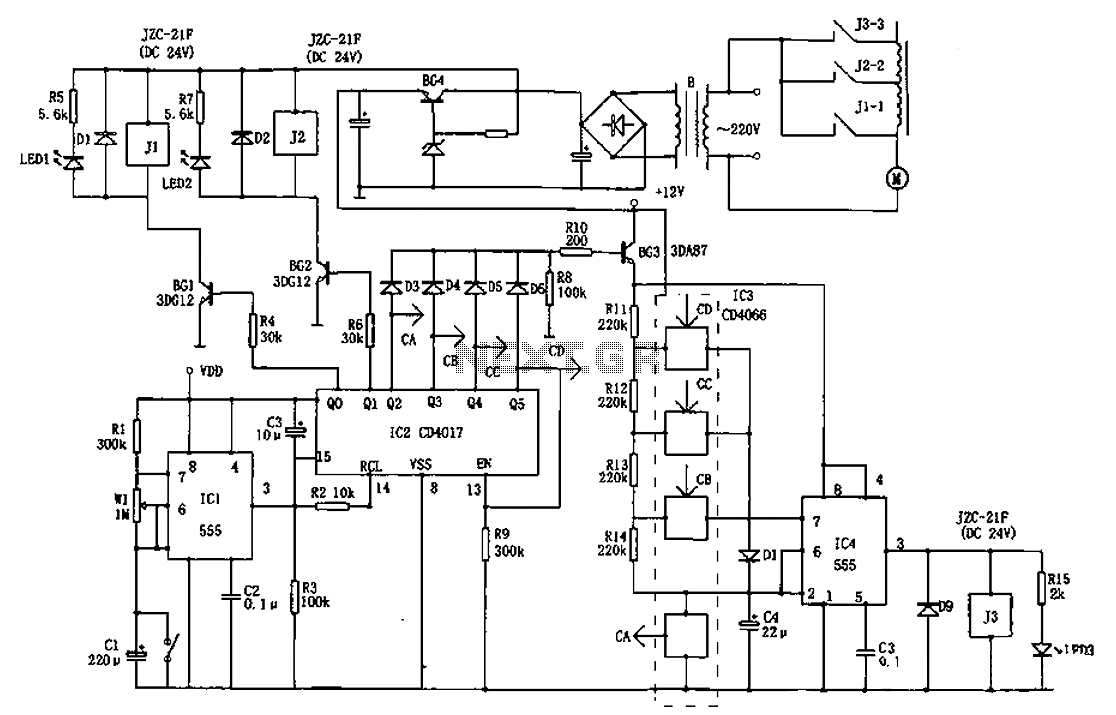
The circuit illustrated in Figure 3-144 depicts an automatic control system for dynamic braking. It utilizes a time relay (KT) to manage the operational duration, along with a step-down transformer (T) and a single-phase bridge rectifier. The circuit includes...
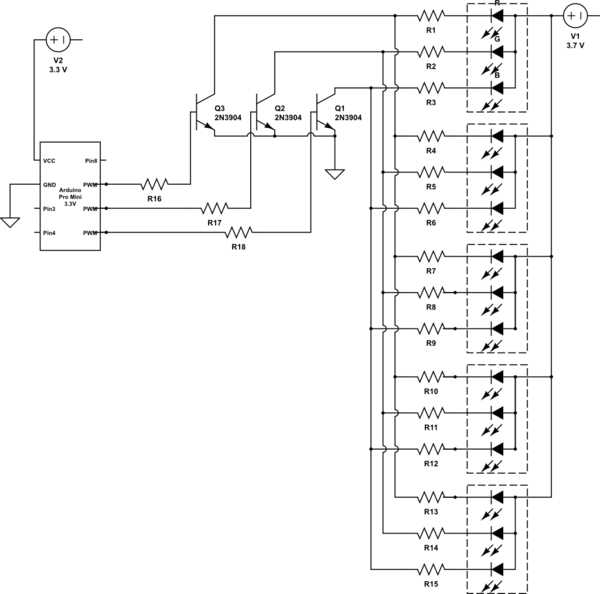
It is noted that the LEDs are not configured in parallel with the transistor. If they were, the LEDs would illuminate when the transistor is off. Instead, the LEDs are connected in parallel before entering the transistor. The transistor...
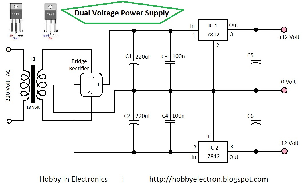
Circuit Home 7809 7812 7909 7912 Dual Voltage Hobby Electronics Hobby electronics projects RC filters REGULATOR transformer Dual Voltage Power Supply 12 Volt This is the simple circuit diagram of a Dual Voltage Power Supply. It is used for...
The AC welder operates intermittently, with power consumption during these periods reaching several hundred watts. The AC welder saving controller circuit enables the welding machine to automatically cut off power during no-load conditions while also automatically restoring power for...
This is a beta release schematic. Use at your own risk. The idea is to add this circuitry to a board that already has RAM at address 2000 and an 82C55 I/O chip to provide ports A, B, and...