
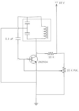
Adjustable oscillator

At this point, the output voltage is -10 V, and the voltage at the inverting terminal continues to decrease according to the same time constant. By adjusting this time constant using a variable resistor, it is possible to generate a variable frequency oscillation.
The circuit utilizes an operational amplifier configured with two feedback paths that enable distinct operational characteristics. The positive DC feedback path is crucial for establishing hysteresis, which is a defining feature of Schmitt triggers. This hysteresis allows the circuit to provide clean transitions between high and low states, effectively filtering out noise and ensuring stable operation.
The CR timing network plays a pivotal role in controlling the rate at which the voltage at the inverting terminal rises. The time constant, denoted as CTRT, is determined by the values of the resistor and capacitor in this network. As the voltage at the inverting terminal increases, it approaches the threshold of +5 V. When this threshold is crossed, the op-amp's output switches from a high state to a low state, resulting in an output of -10 V.
The subsequent behavior of the circuit is influenced by the CR timing network's time constant. As the output voltage drops to -10 V, the voltage at the inverting terminal begins to decrease. The rate of this decrease is governed by the same time constant, allowing for a predictable oscillation pattern. By incorporating a variable resistor in the timing network, adjustments can be made to the time constant, thereby enabling the generation of variable frequency oscillations. This feature is particularly useful in applications requiring signal modulation or waveform generation, showcasing the versatility of this op-amp-based circuit design.In this circuit, there are two feedback paths around an op-amp. One is positive dc feedback which forms a Schmitt trigger. The other is a CR timing network. Imagine that the output voltage is +10 V. The voltage at the noninverting terminal is +15 V. The voltage at the inverting terminal is a rising voltage with a time constant of CTRT. When this voltage exceeds + 5 V, the op amp's output will go low and the Schmitt trigger action will make it snap into its negative state. Now the output is -10 V and the voltage at the inverting terminal falls with the time constant as before. By changing this time constant with a variable resistor, a variable frequency oscillation may be produced.
Related Circuits
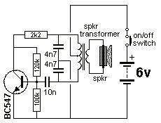
The Colpitts Oscillator is characterized by tapping the mid-point of the capacitive side of the oscillator section. The inductor can be the primary side of a speaker transformer. The feedback comes via the inductor. The Colpitts Oscillator is a type...
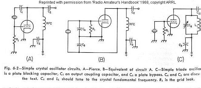
The frequency of a crystal-controlled oscillator is maintained with high precision through the use of a quartz crystal. The frequency is primarily determined by the dimensions of the crystal, particularly its thickness, while other circuit parameters have minimal impact....
This site serves as a collection of useful information that the author wishes to retain, with the occasional inclusion of pages that may be of interest to others. The author has documented the retrofit of the Boxford 125 TCL...
Figure 1 illustrates the VFO oscillator circuit operating within the frequency range of 10.58 to 10.74 MHz. This circuit is a redesigned version of a previously presented Colpitts oscillator, with a clearer representation. The inductor, labeled "L," has an...
The Hartley Oscillator is characterized by an LC circuit in its collector. The base of the transistor is held steady, and a small amount of signal is taken from a tapping on the inductor and fed to the emitter...
An LC Colpitts oscillator is being designed based on the Colpitts oscillator configuration. The LC Colpitts oscillator is a type of electronic oscillator that utilizes an inductor (L) and two capacitors (C1 and C2) to create a feedback loop that...