
Adjustable regulator using L200

The adjustable voltage regulator circuit using the L200 IC is designed for flexibility in output voltage regulation, making it suitable for various applications where precise voltage levels are required. The L200 IC is capable of delivering a stable output voltage with an adjustable range, allowing for customization based on the needs of the connected load.
Resistors R1 and R2 form a voltage divider network, which is critical in setting the desired output voltage. The output voltage (Vout) can be calculated using the formula Vout = Vref × (1 + R2/R1), where Vref is the reference voltage of the L200, typically around 1.25V. By selecting appropriate values for R1 and R2, the output voltage can be finely tuned within the specified range of 2.85V to 15V.
Resistor R3 plays a pivotal role in current limiting, ensuring that the output current does not exceed the specified 1A. This feature protects both the regulator and the connected load from potential damage due to overcurrent conditions. The selection of R3 should be based on the desired current limit and the characteristics of the load.
Capacitors C1 and C2 are essential for maintaining voltage stability and filtering out noise from the power supply. C1 is typically placed at the input to smooth out any fluctuations in the input voltage, while C2 is connected at the output to ensure a clean and stable output voltage. The values of these capacitors should be chosen based on the frequency response requirements of the application.
It is crucial to observe the maximum input voltage specification of 40V for the L200 to prevent damage to the IC. Proper heat dissipation measures should also be implemented, as the regulator may generate heat during operation, especially under high load conditions.
Overall, the L200 adjustable voltage regulator circuit is a robust solution for applications requiring variable voltage outputs, with built-in protections that enhance reliability and performance.Here is the circuit diagram of an adjustable voltage regulator using IC L200. L200 is a monolithic integrated adjustable voltage regulator IC having features like current limiting, thermal shut down, power limiting, input over voltage protection etc. Here the regulator is designed to produce an output adjustable between 2. 85V to 15V at 1A. The resi stors R1 and R2 determines the output voltage. The resistor R3 determines the limiting value of output current, here 1A. Capacitors C1 and C2 does filtering. Do not give more than 40V to the input on L200. 🔗 External reference
Related Circuits
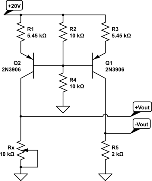
A functional circuit utilizing an operational amplifier (op-amp); however, the instructor indicated that op-amps can be challenging to work with and provided transistors as an alternative. Operational amplifiers (op-amps) are versatile components commonly used in various electronic circuits for...
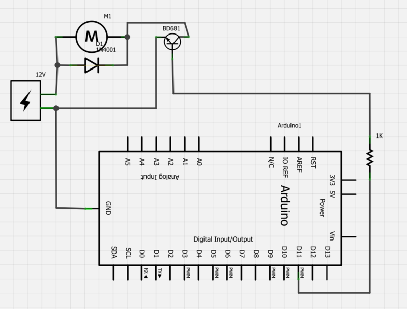
Power a 12V fan using a Darlington transistor to control the speed from an Arduino. When wired as described, nothing happens even though a PWM signal is being sent. It is suggested to edit the question and ensure the...
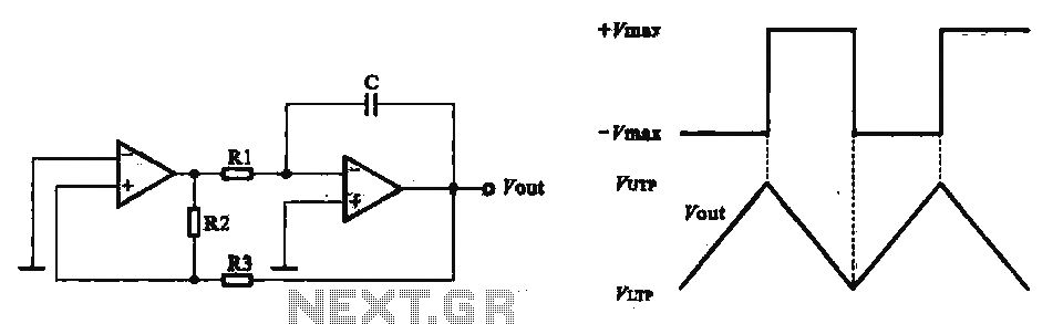
This circuit utilizes two operational amplifiers configured as triangular wave oscillators. It demonstrates a practical application of a relaxation oscillator that employs a voltage comparator to execute the switching function. The schematic in FIG. 2 illustrates the composition of...
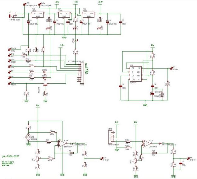
The Arduino 2009 functions as an independent weather station without a display. It can operate autonomously for extended periods, sampling data from sensors until the RAM reaches full capacity. The collected data is stored in a designated sector of...
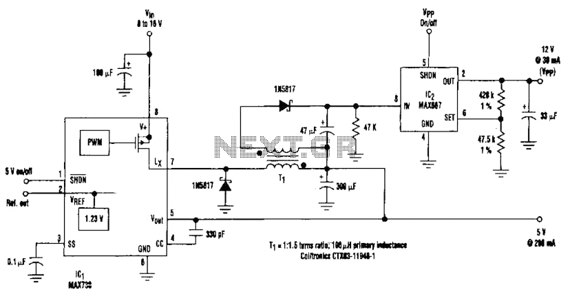
By adding a flyback winding to a buck-regulator switching converter, which functions as a 5-V supply with a 200-mA output capability, a 12-V output can be generated. The flyback winding on the main inductor, forming transformer T1, allows for...
This is the voltage converter to get the voltage of ±1.25-30V from the input voltage of ±35V. I am using the 3 terminal voltage regulator for the voltage to be changed in this unit. As the regulator, LM317 is...