
How do you make a shift/scale circuit using a transistor resistors and a voltage source

Operational amplifiers (op-amps) are versatile components commonly used in various electronic circuits for amplification, filtering, and signal processing. They typically have high input impedance and low output impedance, making them suitable for a wide range of applications. However, they can present complexities in design and stability, particularly when configuring feedback loops or dealing with noise.
Transistors, on the other hand, serve as fundamental building blocks in electronics, functioning as switches or amplifiers. They can replace op-amps in many applications, offering greater simplicity and reliability in certain contexts. A transistor circuit can be designed to achieve similar functionality as an op-amp circuit, albeit with different characteristics.
For a basic transistor amplifier circuit, consider using a common-emitter configuration. In this setup, the transistor's collector is connected to the power supply through a load resistor, while the emitter is grounded. An input signal can be applied to the base of the transistor through a coupling capacitor, allowing AC signals to pass while blocking DC components.
The output can be taken from the collector, where the amplified version of the input signal appears. The gain of the transistor amplifier can be controlled by selecting appropriate resistor values in the circuit. Biasing resistors are also essential to ensure that the transistor operates in the active region, preventing distortion of the output signal.
In summary, while op-amps provide robust solutions for many electronic applications, transistors can serve as effective alternatives, particularly in simpler circuits. Understanding the characteristics and operation of both components is crucial for successful circuit design.A working circuit with an opamp but my professor said that they are hard to work with, and gave me some transistors to use instead. enthdegree May 30 `13 at 17:25 🔗 External reference
Related Circuits
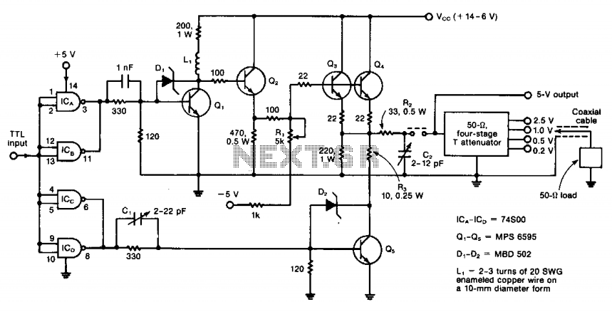
The circuit operates from DC to 50 MHz and is capable of delivering pulses as short as 10 ns. It is driven by a TTL signal through a 740S00 quad Schottky NAND gate, with input connections made via ICA...

This circuit is a simple telephone ringtone generator designed using minimal components. It produces a simulated telephone ringing tone and operates on a DC voltage ranging from 4.5V to 12V. This circuit can be utilized in standard intercom systems...

The pressure transmitter circuit data acquisition system utilizes the 1B31, an 18-bit A/D converter (AD1170), and an MCS-51 microcontroller. The configuration, as depicted in the accompanying diagram, features a full-scale output voltage of 10 mV from the pressure transmitter...
This circuitry facilitates the connection between the computer's Z RS-23 serial interface and the current ring circuitry. It converts the voltage signal of the transmission into a current signal of 20 mA, achieving a maximum speed of 1200 bits....

The circuit utilizes the Trigger and Threshold pins (2 and 6) to monitor maximum and minimum voltage levels. Two voltage comparator operational amplifiers within the 555 timer manage the output state, switching it on or off. The Trigger pin...
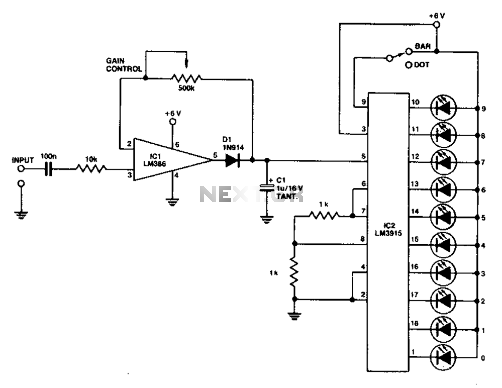
A simple level power meter designed to provide a high-fidelity sound system with a bar or dot matrix display. The green LED display indicates levels from 0 to 7; level 8 is shown in yellow, and level 9 is...