
Adjustable Strobe Light

The Adjustable Strobe Light circuit utilizes a high-intensity "horse shoe" Xenon flash tube, which is capable of producing a significant amount of light output compared to standard strobe lights. The flash rate of this circuit can be adjusted up to approximately 20 Hz, allowing for versatile applications in various lighting scenarios.
Key components of the circuit include a transformer (T1) and an inductor (L1), both of which are available for purchase from The Electronics Goldmine. The circuit design is not isolated from ground, necessitating caution during operation, particularly when the device is not housed in a protective enclosure. It is imperative to use a case during normal operation to prevent accidental contact with high-voltage components.
The circuit employs capacitors C1 and C2, which store energy for the flash tube. It is critical to monitor the operation of the circuit, as excessive use at high flash rates—specifically beyond 30 seconds—can lead to overheating of these capacitors, potentially resulting in failure or explosion.
Diodes used in the circuit should be rated for at least 250 volts and 1 amp to ensure reliable operation. While the schematic does not include an on/off switch, it is advisable to integrate one into the design for enhanced user control and safety.
Overall, this Adjustable Strobe Light circuit offers advanced features and flexibility for users, but it requires careful handling and adherence to safety precautions to ensure reliable and safe operation.This Adjustable Strobe Light is the bigger brother of the plain old strobe light. This one uses a much more powerful "horse shoe" Xenon tube which produces more light. You can also control the flash rate up to about 20Hz. Do not look directly at the flash tube when this thing is on! # T1 and L1 are available from The Electronics Goldmine (see Where To Get Parts). This ciruits is NOT isolated from ground. Use caution when operating without a case. A case is required for normal operation. Do not touch any part of the circuit with the case open or not installed. Most any diodes rated at greater then 250 volts at 1 amp can be used instead of the 1N4004`s. Do not operate this circuit at high flash rates for more than about 30 seconds or else C1 and C2 will overheat and explode. There is no on/off switch in the schematic, but you can of course add one. 🔗 External reference
Related Circuits

The circuit functions as a precision bright light control circuit, operating independently of power supply voltage and ambient temperature. Resistors R1, R2, R6, and the photosensitive resistor R5 form a two-arm Wheatstone bridge. The precision bright light control circuit utilizes...
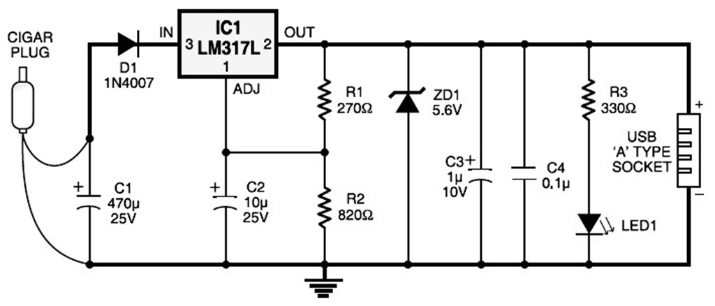
A USB port is capable of supplying more than 100 mA of continuous electric current at 5V to peripherals connected to the bus. This feature allows a USB port to power 5V DC-operated small electronic devices without issues. Many...

FIG. 284 illustrates a practical emergency power lighting system that activates automatically in the event of a sudden power outage. The fluorescent lights serve as emergency lighting. If the primary illumination lamp is turned off due to a power...
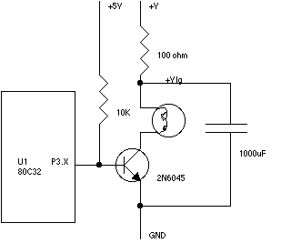
Flight Computer V1.0: B1 PC Board U1 80C32 microprocessor U2 27C256-12 32Kx8 ROM - 120nS U3 74HC373 U4 LM340T-5 5V regulator (may be a 7805 part) U5 43C256-15 32Kx8 RAM - 150nS U6 74HC00 T1-T4 2N6045 or 2N6044 Darlington...

The input attenuator uses a commutating capacitor to cancel the input capacitance of the FET buffer (see DC-10 MHz amp schematic). The commutating capacitors are absolutely necessary to cancel the effect of the input capacitance to the DC-10MHz amplifier....

This is a sensor circuit designed for light detection. It utilizes the LM311 comparator and features a simple design. The comparator is powered by a 12 V DC supply and does not require a negative supply for efficient operation....