
Adjustable Auto transformer

More: The circuit was carefully assembled using crimp connectors for all of the screw-down connections, with proper insulation via heat shrink tubing. All of the pieces of the steel and aluminum box were connected by bonding wire. All of the conductors were taken from 0.5 square mm lamp cord to assure the required dielectric strength. The earth leakage dongle (GFIC dongle) also passes the earth ground through to the output connector.
The described circuit consists of two primary components: an isolation transformer and a variable auto transformer, commonly referred to as a Variac. The isolation transformer serves to decouple the circuit from the mains supply, providing safety by isolating the user from potentially hazardous voltages. The variable auto transformer allows for adjustable voltage output, enabling the user to modify the voltage supplied to connected devices as needed.
Fuse 1 is strategically placed in the circuit to protect against excessive current, effectively acting as a safeguard against gross overload conditions. In the event of a blown fuse, Lamp 1, which is a red incandescent pilot lamp, illuminates to provide a visual indication of the fault condition. This feature is particularly useful when troubleshooting or bringing up power supplies that may be unresponsive.
Safety is a paramount concern in the design of this circuit. All components that may come into contact with the user are connected to earth ground, reducing the risk of electric shock. Additionally, an earth leakage breaker dongle is included in series with the circuit. This device monitors the current flowing through the circuit and disconnects the supply in the event of an earth fault, further enhancing user safety.
The assembly of the circuit is executed with attention to detail, utilizing crimp connectors for all screw-down connections to ensure reliable electrical contact. Heat shrink tubing is employed for insulation, providing protection against accidental short circuits and environmental factors. The structural integrity of the enclosure, constructed from steel and aluminum, is maintained through the use of bonding wire, ensuring that all parts are securely grounded.
Conductors used in the circuit are sourced from 0.5 square mm lamp cord, which is selected to meet the required dielectric strength for safe operation. The earth leakage dongle (GFIC dongle) is designed to pass the earth ground through to the output connector, maintaining the safety features throughout the entire circuit. This comprehensive approach to design and assembly ensures both functionality and safety in operation.An isolation transformer and a variable auto transformer, very much like a Variac. Fuse 1 protects against gross overload. Lamp 1, across the Fuse 1, is a red incandescent pilot lamp and it lights up in the event of a blown fuse. Imagine how much time this would save when bringing up a stubborn power supply. Take note: Everything that can possibly come in contact with the user is connected to earth ground. in practice, I also have a earth leakage breaker dongle in series with this device. The circuit was carefully assembled using crimp connectors for all of the screw-down connections, with proper insulation via heat shrink tubing. All of the pieces of the steel and aluminum box were connected by bonding wire. All of the conductors were taken from 0.5 square mm lamp cord to assure the required dialectic strength.
The earth leakage dongle (GFIC dongle) also passes the earth ground through to the output connector. 🔗 External reference
Related Circuits

The circuit for automatic brightness adjustment in a television utilizes a photosensitive resistor and a contrast potentiometer connected to an intermediate stage. The photosensitive resistor varies its resistance based on light intensity, causing changes in the potential at the...

Although you can obtain universal, resistor-programmable switched-capacitor filters that are configurable as notch filters, most cannot operate at bandwidths higher than 100 kHz. Further, the typically 16- to 20-pin packages do not include a continuous-time, antialiasing filter to prevent...
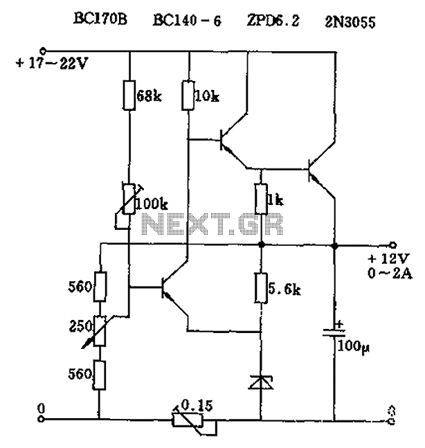
The circuit output voltage can be continuously adjusted from zero to its maximum value. The baseline is established by a constant current sourced from the auxiliary power supply circuit. The reference current of 500 microamperes can be fine-tuned to...

The alarm consists of a diode, buzzer, and a limiting resistor. The diode functions as a switch that enables the buzzer to activate only when the light switch is closed and the ignition is turned off. The circuit described utilizes...

The following circuit illustrates an Automatic Room Power Control Circuit Diagram. This circuit is based on the NE555 integrated circuit (IC). Features include the use of two Light Dependent Resistors (LDRs). The Automatic Room Power Control Circuit utilizes an NE555...

The alarm activates after a 13-second delay and remains active for 1 to 1.5 minutes before automatically resetting. It can also be deactivated and reset by opening and reclosing switch SI. The described circuit functions as a delay-triggered alarm system,...