
Adjustable Vfo Temperature Compensator Circuit

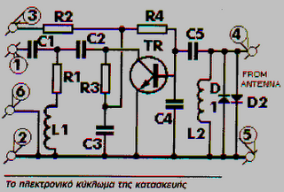
The described circuit employs a differential capacitor, specifically C6, designed to enhance the performance stability of the LC circuit across varying temperature conditions. The differential capacitor's architecture, consisting of two stators and a common rotor, allows for precise adjustments. As the rotor is manipulated, one stator's capacitance increases while the other's decreases, effectively maintaining a balanced capacitance that compensates for temperature-induced variations. This mechanism is critical in applications where frequency stability is paramount, such as in radio frequency (RF) circuits.
The additional components, LI, CI, C2, and C3, serve specific roles in the circuit. LI is typically an inductor that, in conjunction with the capacitors, forms the LC tank circuit essential for resonance. CI, a variable capacitor, is used for fine-tuning the resonant frequency, allowing the circuit to adapt to specific operational requirements. C2 and C3, being a combination of trimming and fixed capacitors, provide necessary adjustments to the overall capacitance, ensuring that the circuit achieves the desired performance characteristics.
In summary, the integration of a differential capacitor within the LC circuit, along with the supporting tuning and trimming capacitors, facilitates enhanced temperature compensation and frequency stability, making it suitable for precision electronic applications. Use of a differential capacitor allows temperature compensation of LC circuit using an NFO and N1500 ceramic. C6 is a differential capacitor that has two stators and one common rotor. When one capacitance (stator) is maximum, the other is minimum. LI, CI, C2, and C3 are tuning, trimming, and fixed capacitors, respectively.
Related Circuits
These frequencies include TV in VHF and UHF, as well as the radio broadcasting frequencies in the 88 - 108 MHz FM band. Component: Resistor, IC. The circuit described operates within the VHF (Very High Frequency) and UHF (Ultra High...

The schematic for this project is not overly complex; however, it is crucial to understand the circuit board and its operation due to the high voltages generated. Below is a rough draft schematic of the camera used for this...
The following circuit illustrates a Water Level Detector Circuit Diagram. This circuit is based on the PIC12F683 microcontroller. Features include the ability of the PIC microcontroller to enter a sleep mode. The Water Level Detector Circuit utilizing the PIC12F683 microcontroller...
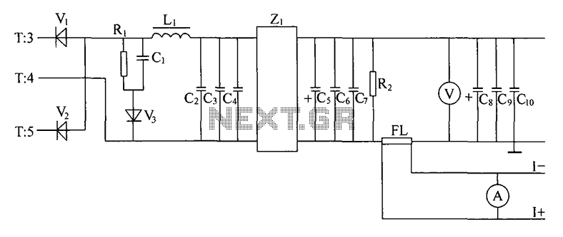
Alternating positive and negative voltage pulses from the secondary winding of a high-frequency transformer (T) are full-wave rectified by high-frequency switching diodes (V1, V2). The output is then filtered through inductors (L1) and capacitors (C2, C3, C4) which form...

This simple temperature relay circuit can be used to signal a fire or setpoint for temperature monitoring function. You need to adjust P1 so that T1's base. The temperature relay circuit operates by monitoring the temperature in a designated area...
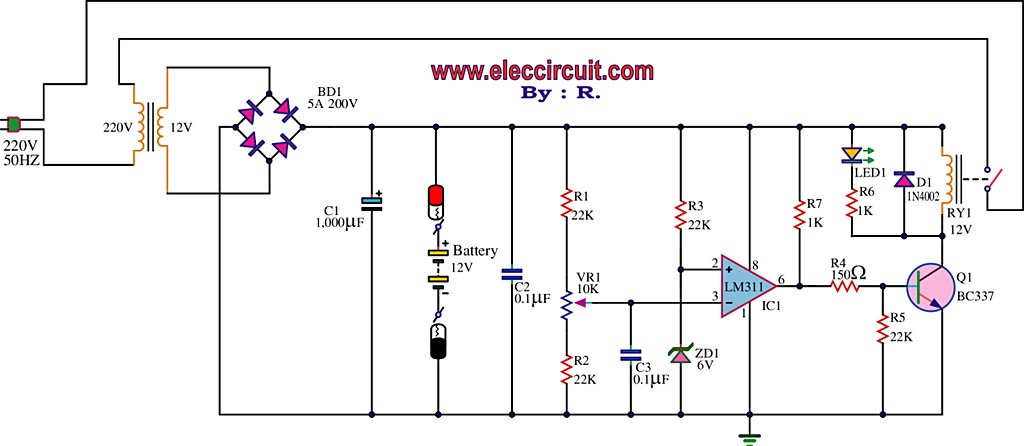
The best 12 Volt battery charger circuit is an automatic system that activates when the battery voltage falls below a specified threshold. This 12 Volt battery charger circuit is designed to efficiently charge lead-acid batteries while ensuring safety and longevity....