
Advanced 1-Wire Network Driver

The schematic details a microcontroller-driven circuit designed to manage extensive 1-Wire networks, which are commonly used for communication and control in various electronic applications. The circuit is engineered to facilitate the connection of multiple 1-Wire devices, enabling them to communicate with a central microcontroller.
The design typically includes a microcontroller unit (MCU) that acts as the primary control hub. This MCU interfaces with the 1-Wire bus, which allows for the connection of numerous 1-Wire devices, such as temperature sensors, memory chips, and other peripherals. The circuit may utilize pull-up resistors on the 1-Wire line to ensure proper signal integrity, as the 1-Wire protocol relies on a single wire for both power and data transmission.
The operation of the circuit is governed by a series of software flowcharts that outline the logic and sequence of operations the microcontroller follows when communicating with the 1-Wire devices. These flowcharts provide a visual representation of the program structure, including initialization routines, data reading and writing processes, and error handling mechanisms.
Additionally, the schematic may include scope traces that illustrate the timing and voltage levels of signals on the 1-Wire bus during operation. These traces are essential for debugging and optimizing the circuit's performance, ensuring that the timing requirements of the 1-Wire protocol are met.
Overall, this microcontroller-based driver circuit is a crucial component for effectively managing large-scale 1-Wire networks, providing the necessary infrastructure for robust communication and control in a variety of applications.Schematic and operation of a microcontroller-based driver circuit for large 1-Wire networks; includes software flowcharts and scope traces.. 🔗 External reference
Related Circuits
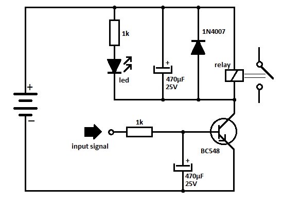
One of the serious problems in relay-operated circuits is the relay clicking or chattering during the on/off operation of the relay driver transistor. This issue can lead to unreliable circuit performance and may cause premature wear of the relay...

Here is a simple and cost-effective Power LED driver circuit. This power LED driver circuit is designed to efficiently drive high-power LEDs with a stable output. The circuit typically consists of a few key components: a power supply, a current...

The software aspect is straightforward due to the Vodafone USB Modem library designed for mbed. This library is compatible with any of the cellular data plans provided by Vodafone. The primary limitation is geographical, as it is only available...
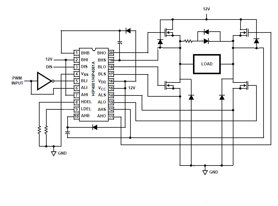
An individual is experiencing an unusual issue while utilizing an Intersil HIP4081A H-bridge driver integrated circuit (IC). The IC is connected to an Arduino microcontroller unit (MCU). The Intersil HIP4081A is a high-performance H-bridge driver designed for driving DC motors...

The circuit illuminates a high-brightness LED even at a voltage of 0.8V if the battery can supply 93mA at this voltage. The average step-up efficiency from 0.8V to 1.5V is 75%, with a peak efficiency of 83% occurring around...
A simple, time-honored approach is to use one or more 74AC245 chips (normally the 74AC245 is used for maximum current capability) to provide motor drive current. Here, each channel of drive power is provided by one or more buffer...