
Advanced Triangular wave generator

The triangular wave generator is an essential component in various electronic applications, including signal processing, waveform generation, and testing. This circuit typically utilizes operational amplifiers (op-amps) or comparators to create a stable triangular waveform.
The core functionality of the triangular wave generator involves charging and discharging a capacitor through a resistor. The charging phase occurs when the capacitor is connected to a voltage source, causing it to ramp up linearly until it reaches the maximum peak level. At this point, a comparator detects the voltage level and switches the connection, allowing the capacitor to discharge through another resistor. This discharge phase results in a linear drop in voltage until the minimum peak level is reached, at which point the cycle repeats.
The circuit diagram for a triangular wave generator usually includes the following components:
1. **Operational Amplifier**: Used to amplify the signal and maintain stability in the waveform.
2. **Capacitor**: Stores charge and determines the frequency of the output waveform based on its capacitance value.
3. **Resistors**: Control the charging and discharging rates of the capacitor, which directly influence the frequency and shape of the triangular wave.
4. **Comparator**: Monitors the voltage across the capacitor and toggles the charging and discharging paths.
Key parameters that can be adjusted in the design include the values of the resistors and capacitors, which affect the frequency and amplitude of the output waveform. Additionally, the supply voltage can be varied to achieve different peak levels.
In summary, the triangular wave generator circuit provides a reliable method for generating triangular waveforms with adjustable peak levels, making it a versatile tool in electronic design and testing.Triangular wave generator in this website has more advantage triangular wave with maximum peak level and minimum peak level circuit diagram and description of triangular wave generator. 🔗 External reference
Related Circuits
Power input is to a 7805 5 volt regulator. A pair of LEDs is connected between the 5 volt supply and ground, with current limiting resistors in series and one pin on the AT90S2313 shunts the current through one...

In typical push-pull driver applications, the NPN-PNP transistor pair is alternately activated and deactivated using a square-wave signal. A basic driver circuit employs an inverter between the V1 and V2 inputs to toggle the output transistors. However, mismatched turn-on...
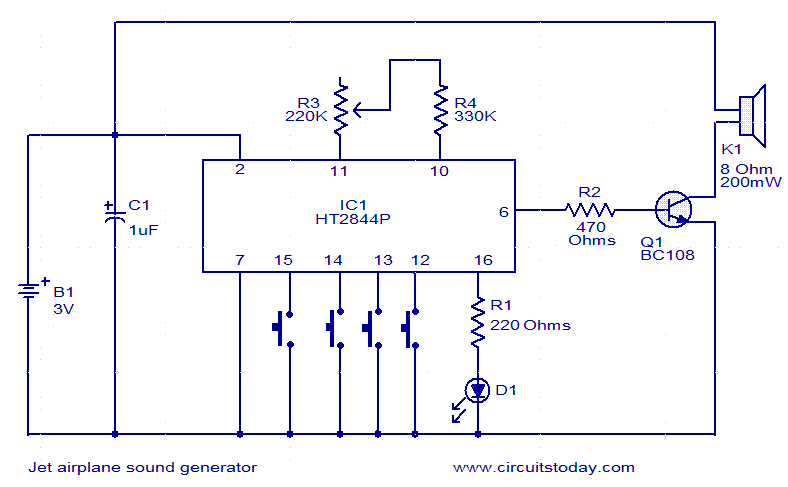
This jet engine sound generator circuit utilizes the sound generator IC HT2844P from Holtek Semiconductors. The IC is capable of producing four distinct sounds: the low-speed sound of a jet engine, the high-speed sound of a jet engine, a...
This circuit is a Wien Bridge Sine Wave Oscillator. The primary challenge in generating a low distortion, constant amplitude sine wave is to achieve the appropriate loop gain in the amplifier. By utilizing the 2N3069 JFET as a variable...
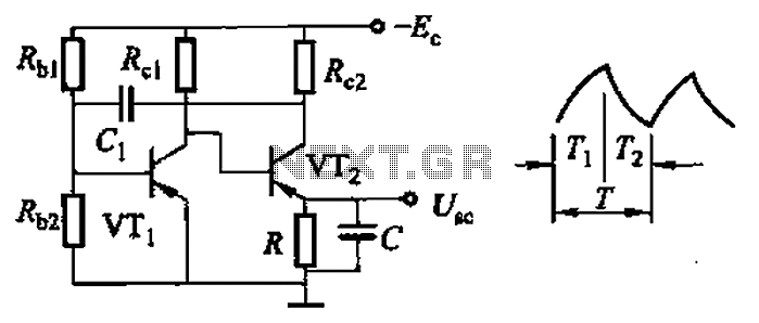
Common non-sinusoidal oscillator circuit, waveform and frequency formula - sawtooth oscillator - use multivibrator. The sawtooth oscillator is a type of non-sinusoidal waveform generator that produces a triangular or sawtooth-shaped output signal. This oscillator is commonly utilized in various applications,...
The interval between rings can be adjusted by changing the value of the 1 Meg resistor. A 70 volt, 30 Hz ringing voltage is generated from the 120 volt side of a small 12.6 VAC power transformer (Radio Shack...