
Advanced version of Joule Thief circuit

In electronic circuit design, particularly when dealing with light-sensitive applications, the accurate measurement of light intensity is crucial. A light meter serves as an essential tool in this context, providing precise quantification of light levels that can significantly influence circuit performance and component selection.
The light meter operates by converting light energy into an electrical signal, which can be displayed in various units such as lux or foot-candles. This measurement allows engineers to determine the optimal operating conditions for light-sensitive components, such as photodiodes, phototransistors, or light-dependent resistors (LDRs).
In designing circuits that rely on ambient light levels, such as automatic lighting systems or solar-powered devices, integrating a light meter can enhance reliability and efficiency. For instance, in a circuit where a phototransistor is used to control an LED based on light levels, the data obtained from the light meter can be used to calibrate the sensitivity of the phototransistor. This ensures that the LED only activates under specific light conditions, thereby conserving energy and prolonging the lifespan of the components involved.
Furthermore, the light meter can assist in troubleshooting and optimizing existing circuits. By providing real-time feedback on light levels, engineers can make informed adjustments to component values or configurations, ensuring that the circuit operates within its intended parameters.
In summary, the incorporation of a light meter into circuit design and analysis is a valuable practice that enhances the accuracy of light level assessments, ultimately leading to more effective and efficient electronic systems.When working with these circuits, I bought a light-meter to take the guesswork out of assessing light levels as the human eye is very bad at doing that. 🔗 External reference
Related Circuits
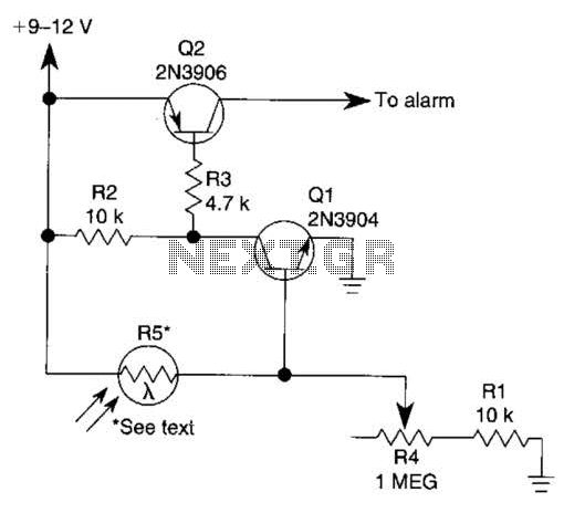
The circuit functions as a sensor capable of triggering an alarm without direct contact from an intruder. It utilizes a visible or invisible light source that illuminates the sensor, maintaining the detection loop in a normally closed state. As...
This automatic NiCd charger for 9V NiCd batteries utilizes the properties of a 555 timer and is straightforward to construct. The charger is designed to automatically maintain a full charge on the battery, allowing it to remain connected for...

This design outlines a tracking transmitter for audio tones operating in the FM band frequency. The circuit can function as either a signal transmitter or a remote control transmitter and utilizes only readily available components. It has a transmission...

Q1 is a PNP power transistor used in conjunction with a ferrite transformer to form a blocking-type oscillator. This oscillator operates at a fixed frequency, with feedback for sustaining oscillations provided by capacitor C1. Due to the turns ratio...
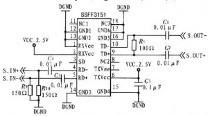
An article previously discussed connecting to the Raspberry Pi board from a Linux PC using the serial port. This time, the focus is on how to achieve the same connection using a Windows PC. In this case, a Windows...
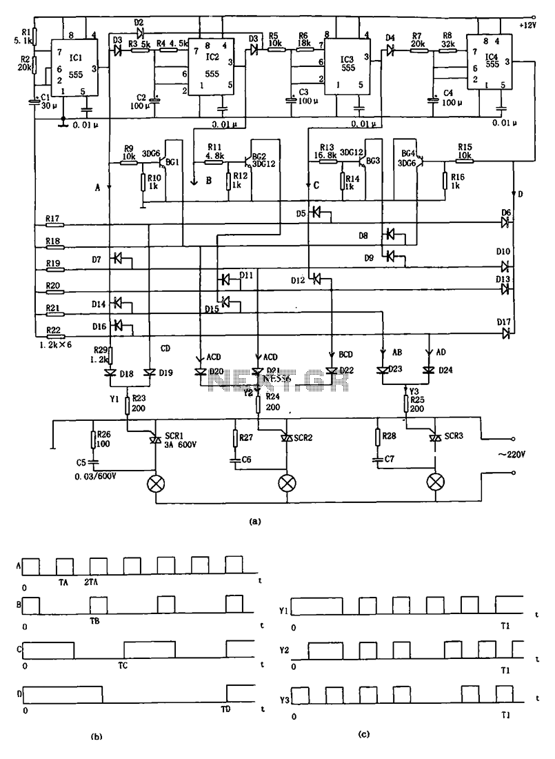
The decorative lamp control circuit is illustrated in the figure. The controller comprises a pulse generator, a frequency divider, a matrix circuit, and a thyristor control circuit. Components IC1, R1, R2, C1, and others form a multivibrator where the...