
Circuit schematicof 1.25G optical transceivers SSFF315l

To connect a Windows 8 PC to a Raspberry Pi using a USB to RS-232 adapter, the setup requires a few essential components: a Raspberry Pi board, a USB to RS-232 adapter, a Windows 8 PC, and the Tera Term terminal emulator software. The USB to RS-232 adapter serves as the bridge between the PC's USB port and the Raspberry Pi's serial communication interface.
The connection process begins with installing the necessary drivers for the USB to RS-232 adapter on the Windows PC. Once the drivers are installed, the adapter is connected to an available USB port on the PC. The RS-232 end of the adapter is then connected to the Raspberry Pi's RS-232 board, ensuring that the connections are secure.
Next, Tera Term must be downloaded and installed on the Windows PC. Upon launching Tera Term, the user selects the appropriate serial port that corresponds to the RS-232 adapter. The default settings for the serial connection typically include a baud rate of 115200, 8 data bits, no parity, 1 stop bit, and no flow control. These settings must be confirmed to ensure proper communication between the PC and the Raspberry Pi.
Once Tera Term is configured and the Raspberry Pi is powered on, the boot-up messages will be displayed in the Tera Term window. This output confirms that the serial connection is functioning correctly. After the boot process is complete, the user can log into the Raspberry Pi by entering the appropriate credentials directly into the Tera Term interface. This method allows for remote access to the Raspberry Pi without the need for a physical keyboard or monitor connected to the device, streamlining the setup for headless operation.
In summary, this connection method provides an efficient way to interface with the Raspberry Pi using a Windows PC, utilizing standard serial communication protocols and open-source software to facilitate the interaction.Previously, an article was posted on how to connect to the Raspberry PI board from a Linux PC using the serial port. We now look at how to do the same thing using a Windows PC. In this article, a Windows 8 PC is connected to the Raspberry PI through a USB to RS-232 adapter and Raspberry PI RS-232 board.
The open-source terminal emulator softwar e Tera Term is then used to connect to the PC`s RS-232 serial port. Once Tera Term is connected to the serial port and the serial port plugged into the Raspberry PI, when the Raspberry PI is powered up, the boot-up messages will be seen in Tera Term. After booting, the Raspberry PI can be logged into by typing in Tera Term ” no keyboard or screen needs to be plugged into the Raspberry PI.
The only thing plugged into the RPI is the serial adapter and power cable. 🔗 External reference
Related Circuits
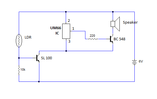
This article provides instructions for creating a light-sensitive morning alarm circuit. The circuit utilizes an LDR (Light Dependent Resistor) or photoresistor to detect morning light, which triggers the alarm section. When light is detected, the circuit produces a melodious...
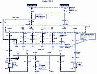
The section of the 1996 Ford Windstar wiring diagram includes details on power distribution, common connections, rear circuits, ignition systems, the fuse panel, battery connections, instrument illumination, radio wiring, left rear speaker connections, remote headphone module, solid-state components, and...

This electronic schematic allows for the design of a simple cellular phone detector circuit capable of sensing the presence of an activated mobile phone from a distance of 1.5 meters. The capacitor C3 should have lead lengths of 18...

The following circuit illustrates a Video and DVD Modulator in a VHF/UHF electronic diagram. Features include an oscillator that utilizes a transistor for high-frequency operation. The video and DVD modulator circuit serves to convert video signals into a format suitable...

The circuit of a loop sensor-based simple security alarm is described here. The sensor loop consists of a short length of thin enamelled copper wire. The loop sensor security alarm operates on the principle of detecting interruptions in the circuit...

A simple level power meter designed to provide a high-fidelity sound system with a bar or dot matrix display. The green LED display indicates levels from 0 to 7; level 8 is shown in yellow, and level 9 is...