
air craft receiver

This circuit design focuses on creating a straightforward and accessible receiver capable of tuning into the 220 MHz to 400 MHz frequency band used for aircraft communications. The schematic typically includes a few essential components: an antenna, a radio frequency (RF) amplifier, a mixer, and a demodulator.
The antenna, which is crucial for capturing the RF signals, should be designed to operate efficiently within the specified frequency range. A dipole antenna or a quarter-wave monopole antenna can be effective choices, depending on the desired portability and ease of construction.
The RF amplifier is responsible for boosting the weak signals received by the antenna. A low-noise amplifier (LNA) is often used to enhance the signal strength without significantly adding noise, ensuring that the subsequent stages of the circuit receive a clear signal.
Next, the mixer combines the amplified RF signal with a local oscillator signal to convert the frequency of the incoming signal to a lower intermediate frequency (IF). This process allows for easier filtering and demodulation. The choice of the local oscillator frequency is critical, as it determines the tuning capabilities of the receiver.
The demodulator then extracts the audio information from the IF signal. A simple envelope detector can be employed for amplitude modulation (AM) signals, which are commonly used in aircraft communications. If frequency modulation (FM) is utilized, a dedicated FM demodulator circuit may be necessary.
Finally, the output can be connected to a speaker or headphones, allowing users to listen to the communications. Additional components such as variable resistors can be included in the circuit to adjust the volume and improve user experience.
In conclusion, this circuit provides an accessible means for enthusiasts to engage with aircraft communications, making it a valuable project for hobbyists interested in radio technology. Proper construction and tuning of the circuit will ensure optimal performance and enjoyment.The communications between commercial aircraft and the ground can be interesting, amusing and sometimes even disturbing. However radios that receive the approximately 220MHz to 400MHz band commonly used for aircraft (both military and commercial) are not easily found.
And scanners can be complicated, large and expensive. With an easy to build circ uit such as this one, everyone can enjoy listening in on these conversations. 🔗 External reference
Related Circuits
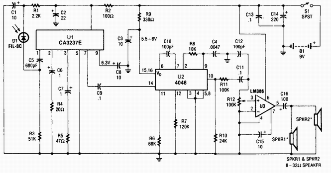
A photodiode D1 feeds a high-gain infrared (IR) remote control preamplifier IC, specifically a CA3237E. U2 is a phase-locked loop (PLL) frequency modulation (FM) detector tuned to approximately 100 kHz. The output from the detector is amplified by U3,...
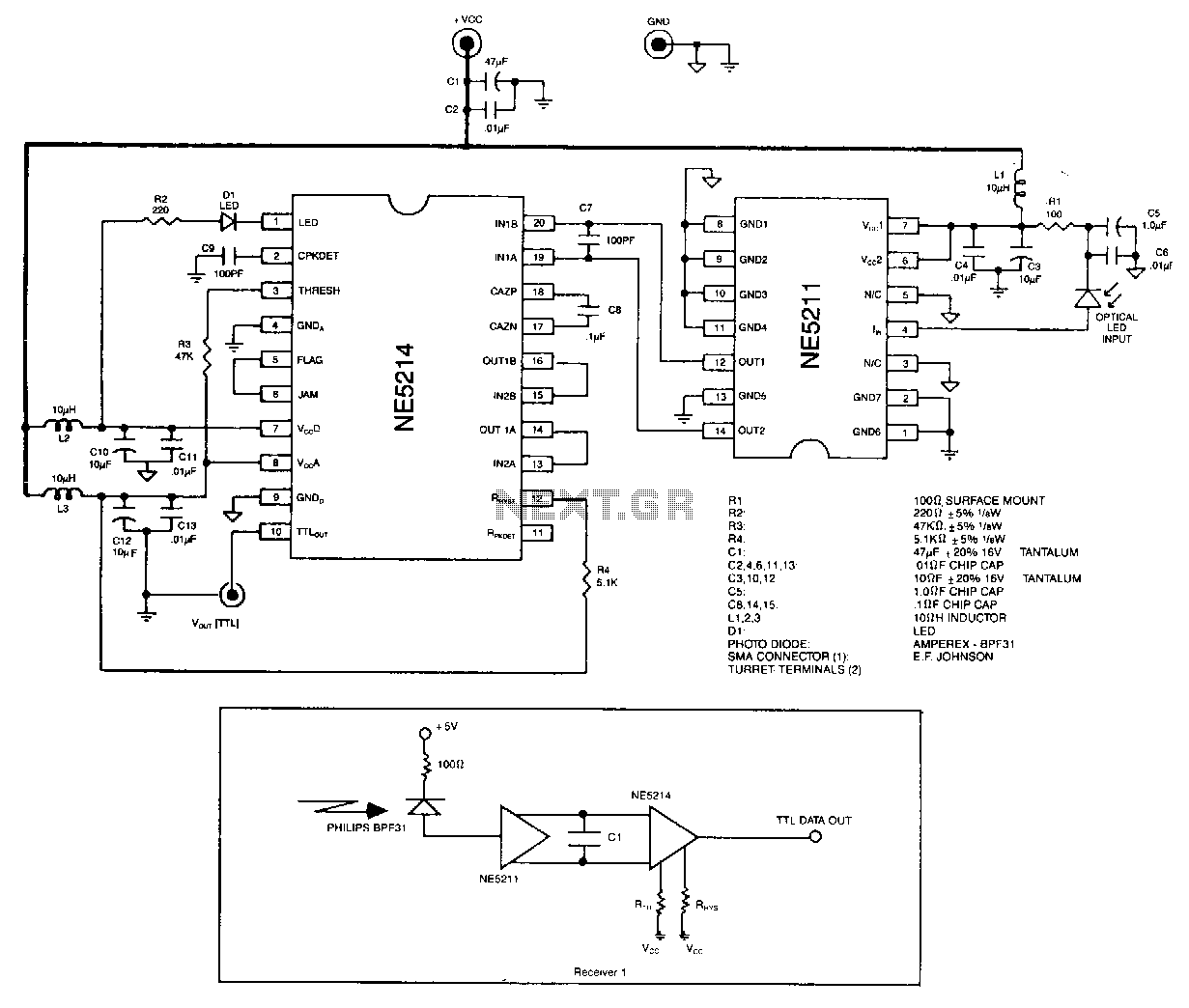
The optical signal is coupled to the pin diode. Current flowing in the diode also flows into the input of the NE5211 preamplifier. The preamplifier is a fixed-gain block that has a 28 kΩ differential transimpedance and performs a...
The regenerative detector uses a field effect transistor (FET). Like with the better valve designs, feedback is controlled by a variable capacitor. A ferrite rod was used to allow reception of local stations without an external antenna. This FET...
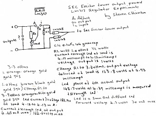
The following experiment demonstrates how Mr. Steven successfully extracted free energy from air using his home-built secondary exciter coil tower. He utilized this energy to power a small LM317 power supply unit. During the process, he hand-wound his coils...
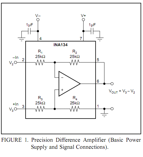
Burr-Brown DRV134 audio balanced line receiver schematic PCB/kit available? There is an interest in creating a balanced line receiver using the DRV134. The Burr-Brown DRV134 is an integrated circuit designed for audio applications, specifically for converting unbalanced audio signals...
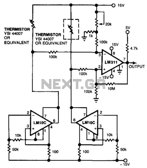
Using a thermistor-bridge circuit, it is possible to detect air losses in system cooling caused by filter or inlet blockage or fan failure. One thermistor is placed directly in the airflow, while the other is shielded. The exposed thermistor...