
wireless ir headphone receiver

The circuit begins with the photodiode D1, which serves as the light-sensitive element that detects infrared signals emitted by a remote control. When IR light strikes the photodiode, it generates a small photocurrent proportional to the intensity of the incoming light. This current is then fed into the high-gain preamplifier IC, CA3237E, which amplifies the weak signal from the photodiode to a more usable level.
Subsequently, the amplified signal is sent to the PLL FM detector, designated as U2. This component is tuned to a frequency of around 100 kHz, allowing it to demodulate the frequency-modulated signal received from the preamplifier. The phase-locked loop configuration ensures that the output remains synchronized with the incoming signal, providing a stable and reliable detection of the transmitted data.
The output from the PLL detector is then processed by U3, which serves as an additional amplification stage. This stage is critical for driving audio output devices such as speakers or headphones. The amplification ensures that the audio signal is sufficiently strong to be heard clearly when played through these devices.
Overall, this circuit design effectively combines photodetection, signal amplification, and audio output, making it suitable for applications in IR remote control systems. The careful selection of components and their configuration allows for efficient signal processing and reliable performance in various electronic devices.A photodiode Dl feeds high gain IR remote control preamp 1C, a CA3237E. U2 is a PLL FM detector tuned to around 100 kHz. The detector output is amplified by U3 and it can drive a speaker or a set of headphones. 🔗 External reference
Related Circuits
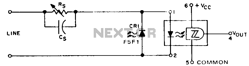
When digital data is transmitted over long distances (greater than 1 meter), the integrity of the transfer can be compromised by parasitic effects such as ground level shifts and ground loops, in addition to extraneous noise that may be...
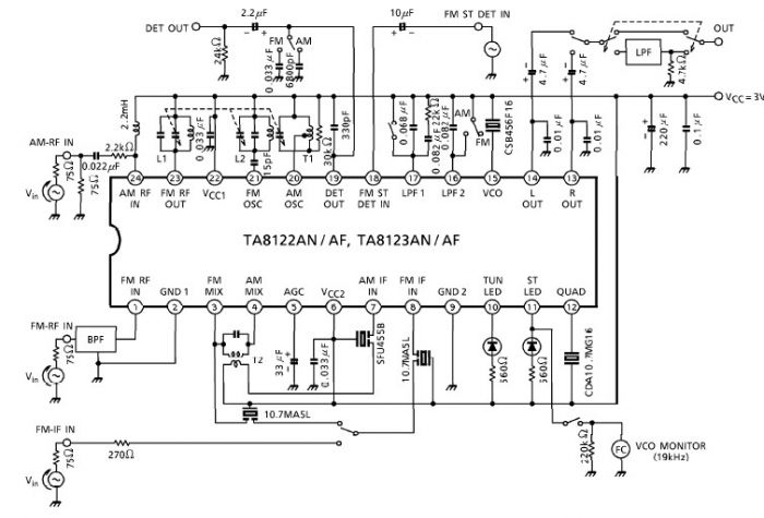
A simple low-power AM/FM radio receiver electronic project can be designed using the TA8122 integrated AM/FM receiver, manufactured by Toshiba Semiconductor. This radio receiver circuit is suitable for portable radio applications and similar devices. The TA8122 radio receiver circuit...
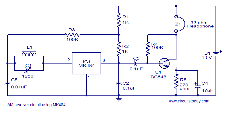
A cost-effective and straightforward AM receiver circuit utilizing the MK484 integrated circuit. The circuit requires minimal external components and operates within a frequency range of 150 kHz to 3 MHz. The MK484 AM receiver circuit is designed for simplicity and...
The concept of a "crystal radio" is typically linked with large antennas and radio broadcasting on long and medium bands. This article discusses experimentally tested detector circuits for VHF receivers designed to listen to FM stations. The discovery of...
High-quality amplifier for headphones electronics project. No need for preamplifier. Circuit diagram. The described project involves the design of a high-quality headphone amplifier that operates without the necessity of a preamplifier stage. This simplifies the circuit while still delivering superior...
A stereo power amp designed for use in portable players and radios. A 3V supply can be used to drive headphones providing 20mW in 32 Ohms per channel. A 9V supply will provide 1W in 8 Ohm per channel...