
alarm door bell circuit using ic um 66 part 1

This circuit utilizes a push-button switch to initiate playback of an audio signal generated by an integrated circuit (IC). The functionality hinges on the interaction between the capacitor C1, resistor R1, and transistor Q2. Upon pressing the push-button switch, C1 begins to charge, creating a voltage that turns on transistor Q2. This transistor acts as a switch, allowing current to flow from the power source to the speaker, thus enabling sound output.
The discharge time of capacitor C1, which directly influences the duration of the audio playback, is controlled by the resistor R1. By varying the resistance value of R1, the time constant of the RC (resistor-capacitor) circuit can be adjusted. A larger resistance value will result in a longer discharge time, allowing the IC to play for an extended period, while a smaller resistance will shorten the playback duration. This feature provides flexibility in the circuit's operation, accommodating different user preferences for audio playback length.
Transistor Q2 is selected based on its ability to handle the current required by the speaker. It should have sufficient gain and current rating to ensure reliable operation without distortion of the audio signal. The circuit may also include additional components such as diodes for protection against back EMF generated by the speaker, ensuring the longevity of the transistor and IC.
Overall, this design offers an efficient and user-friendly approach to audio playback, making it suitable for various applications where controlled sound output is needed.This is a slight modification of that circuit. In the previous circuit you have to keep the switch pressed for making the IC play the full music. Here if once the push button is pressed C1 is charged and the transistor Q2 will keep the IC playing the music till it ends. The time for the IC to play depends on discharging time of C1 which can be se t by R1. Set R1 to select your time, whether full tone or a part in one press. Transistor Q2 drives the speaker. 🔗 External reference
Related Circuits
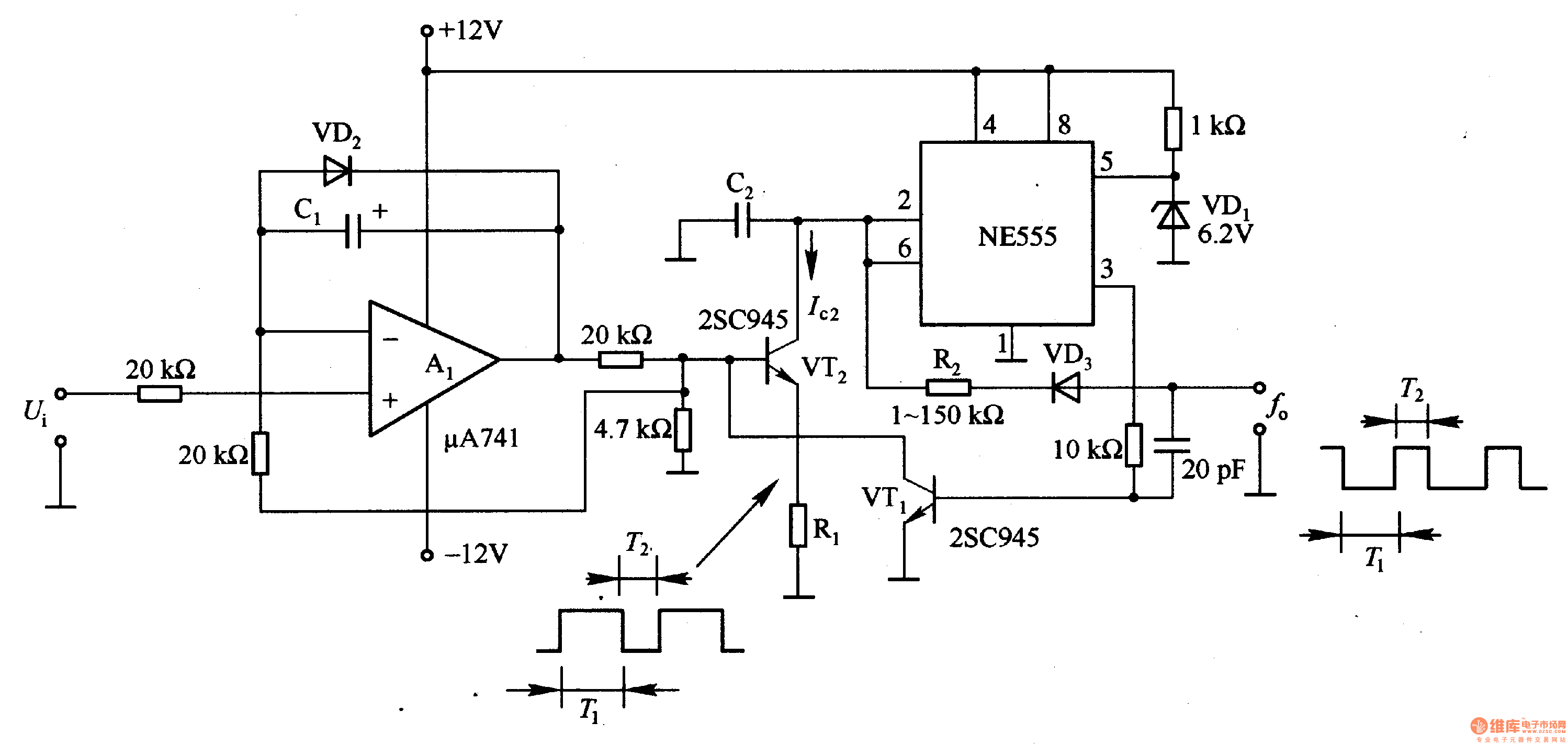
In the circuit, the oscillation frequency of the NE555 is controlled by VT2. When the output at pin 3 is low (during the T1 period), VT1 stops conducting, and VT2 begins to conduct with a current Ic2 flowing through...
This is a programmable clock timer circuit that utilizes individual LEDs to display hours and minutes. Twelve LEDs can be arranged in a circular pattern to represent the 12 hours on a clock face, while an additional 12 LEDs...
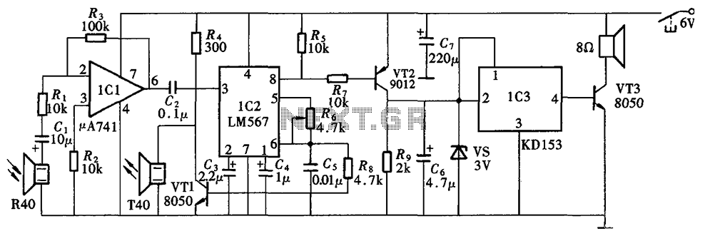
The Blind Pathfinder circuit primarily consists of the A741 operational amplifier, LM567 phase-locked loop, KD153 transistor, 8050 transistor, 9012 transistor, and various other components. The Blind Pathfinder circuit is designed to assist in navigation and obstacle detection, typically utilized in...
The output of this circuit is push-pull and consumes less than 3 mA (with no signal) but drives the earpiece to a very loud level when audio is detected. This circuit operates in a push-pull configuration, which allows it to...
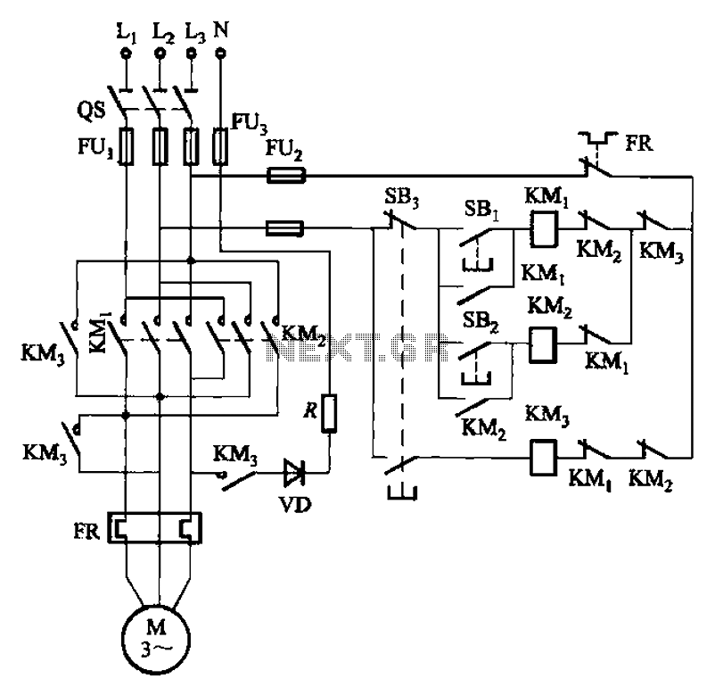
The circuit illustrated in Figure 3-145 employs a rectifier diode brake for neutral grounding in a three-phase, four-wire power supply system. This circuit design incorporates a rectifier diode brake, which plays a crucial role in ensuring the safety and reliability of...
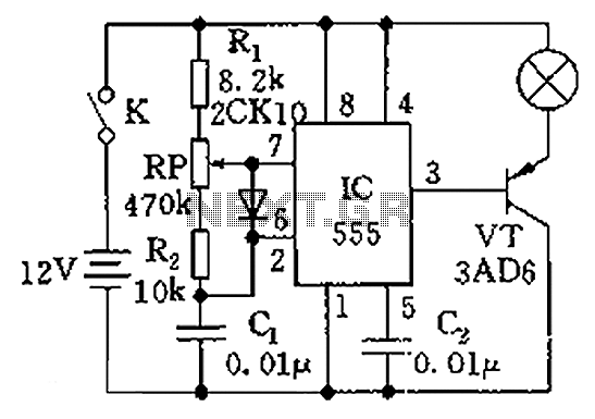
The circuit illustrated in the figure is a dimmer using the 555 timer as the core component. The 555 timer, along with resistors R1, RP, R2, and capacitor C1, forms an astable multivibrator. The oscillation frequency, f, is calculated...