
Low impedance pre amp circuit diagram

The preamplifier circuit is designed to achieve high gain, making it suitable for applications requiring signal amplification from low-level sources. The use of a trimmer resistor (R3) allows for fine-tuning of the gain, providing flexibility in adjusting the amplification to meet specific requirements. The series configuration of R3 ensures that the gain can be decreased as needed, which is particularly useful in preventing saturation or distortion of the amplified signal.
Powering the circuit with a voltage supply between 9 and 18 volts offers versatility, allowing it to be integrated into various systems where different power supply voltages are available. This range provides sufficient headroom for the operational amplifier or transistor used in the preamplifier, ensuring optimal performance across different operating conditions.
The circuit layout should be followed closely to ensure proper functionality. It is essential to pay attention to the orientation of components, particularly polarized capacitors and diodes, as incorrect placement can lead to circuit failure. The layout should also consider minimizing noise and interference, which can be achieved through careful routing of signal and power traces, as well as grounding practices.
In summary, this preamplifier circuit is designed for high gain with adjustable output through a trimmer resistor and is capable of operating within a specified voltage range, making it a versatile choice for various electronic applications.The amplification of this pre amp is therefore very high, whether to reduce, there should be a trimmer R3 series to 100 ohms. The system can be powered by a voltage of between 9 and 18Volts. for its realization, follow the diagram layout. 🔗 External reference
Related Circuits
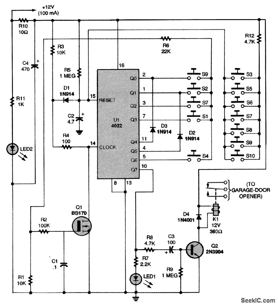
This circuit relies on the input of a correct sequence code. An incorrect number that is not part of the code triggers a reset of the circuit. When the correct code is entered, Q2 activates relay K1 for a...
Having found a u664b prescaler chip (Telefunken) from an old TV tuner, I decided to build a valid frequency counter using PIC16F84. The prescaler I use is able to divide by 64 every frequency from 30 to 1300 MHz....
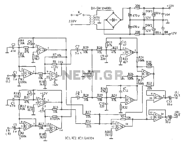
The tape output circuit processes the left and right channel signals through a first buffer amplifier. The output signal is split into two paths: one route directly connects to an amplifier for amplification, while the other route passes through...
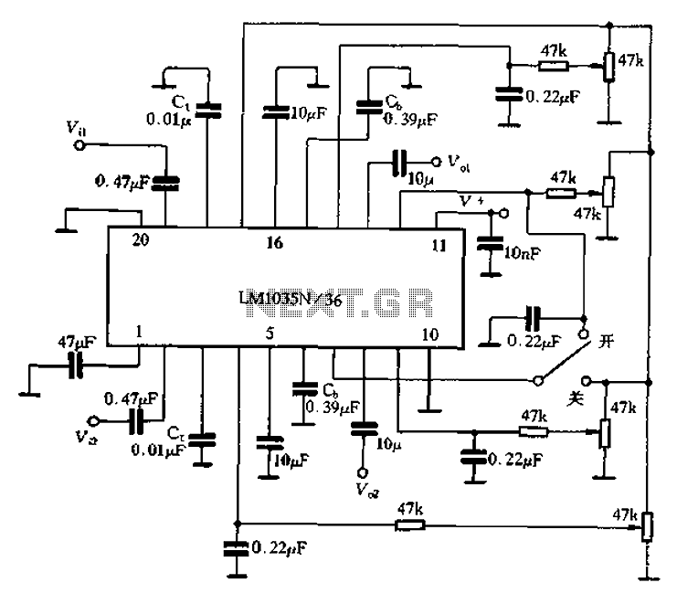
The circuit includes a loudness compensation control terminal at pin 7, which, when combined with the DC control voltage, forms a simple loudness compensation mechanism that enhances bass response. When the loudness control switch is in the OFF position,...
2012 Honda Odyssey Radio Wiring Diagram Manual PDF Download. The 2012 Honda Odyssey Radio Wiring Diagram Manual provides a detailed schematic of the audio system's wiring configuration for the vehicle. This manual is essential for understanding the connections and functionalities...

A field strength meter utilizing a biased Schottky detector employs a temperature-compensated Schottky diode within an amplified, untuned field strength indicator powered by two AA cells. This device indicates the relative field strength of RF fields ranging from a...