
From power fluctuations of one single-junction transistor trigger circuit

The described circuit operates by converting trapezoidal wave voltage into a series of small rectangular pulses that can be synchronized with an external power grid. The synchronization is achieved through a DC chopper, which operates at zero-voltage switching, reducing switching losses and improving efficiency. The 555 timer IC is configured in a comparator mode, which ensures that the output pulses maintain a consistent width despite fluctuations in input voltage.
The use of a low threshold voltage comparator minimizes the influence of voltage variations, allowing the circuit to maintain stable operation even under changing conditions. This design feature not only enhances the reliability of the circuit but also broadens the operational range of phase shifts, which is critical in applications where precise timing is essential.
The circuit's power supply stability is ensured by the 7812 voltage regulator, which outputs a fixed 12V, providing a reliable voltage source for the 555 timer and other components. The inclusion of an adjustment potentiometer (RP) enables fine-tuning of the output pulse width, allowing for precise control over the phase shift angle. This adaptability is particularly beneficial in applications requiring synchronization with varying grid frequencies.
Overall, the circuit design effectively addresses the challenges associated with voltage fluctuations and phase shift management, making it suitable for various electronic applications where synchronization with grid power is crucial. Both circuits can trapezoidal wave voltage synchronous Here is converted into intermittent small rectangular pulse. Its working principle is to make periodic operating in synch ronization with the grid frequency of the zero volt switching voltage of the DC chopper. As a result of the low threshold voltage than the comparator, the impact of voltage fluctuations intermittent sync pulse width is minimal. Therefore, it makes the phase shift angle powered affect network voltage fluctuations greatly reduced, but also expanded phase shift range.
Circuit shown in Figure 16-10. It uses 555 IC Ai limit for single inverter voltage comparator; using 7812 three terminal integrated voltage regulator A2 fixed to provide a stable power supply. Adjustment potentiometer RP, can change the output pulse to e phase shift angle.
Related Circuits
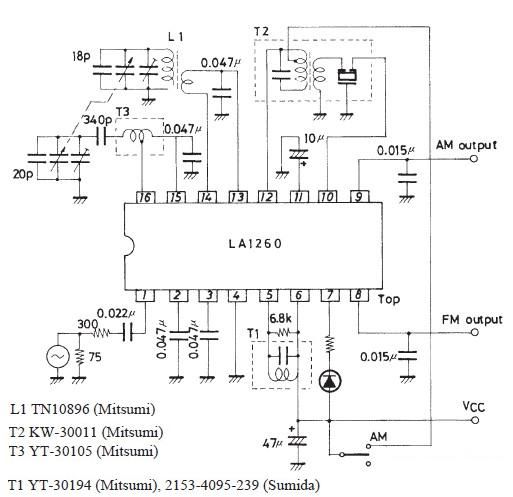
The FM IF MW radio receiver circuit schematic utilizes the LA1260 integrated circuit (IC) for AM and FM radio receiver electronic projects. The LA1260 incorporates numerous functions and features essential for radio receiver applications, including a high signal-to-noise ratio...
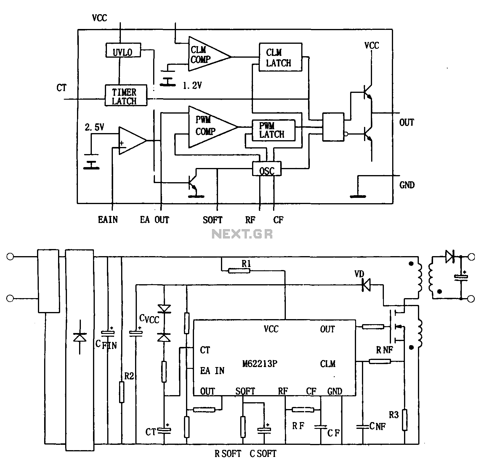
Figure (a) illustrates a block diagram of the internal architecture of the M62213FP, which is a high-speed switching power supply controller. This device includes an oscillator, PWM comparator, error amplifier, output circuit, over-voltage protection, timing latch circuit, over-current protection...
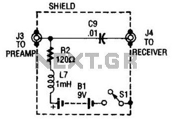
The purpose of the receiver/interface circuit is to pass RF to the receiver through capacitor C9, while adding DC power to the feedline through resistor R2 and RF choke L7. The receiver/interface circuit is designed to facilitate the transmission of...
The circuit was originally available in kit form from a surplus supplier, but it is likely more widely accessible now. It introduces innovative concepts such as utilizing a 555 timer as a pulse width modulator (PWM) and employing serial/parallel...
This is a HiFi pre-amplifier circuit diagram with low noise output. It offers a very wide frequency range from approximately 10 Hz to 100 kHz, which enhances audio performance. The HiFi pre-amplifier circuit is designed to amplify weak audio signals...
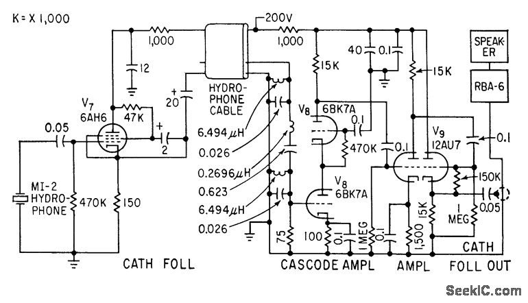
A cathode-follower hydrophone isolation amplifier and high-gain preamplifier are used to feed the Navy RBA-6 low-frequency radio receiver on a trawler. This setup is designed to receive a modulated 21-kc beam that transmits data regarding trawl net depth. The...