
Alternating Relay Switch

The described circuit utilizes a monostable relay configuration, which is essential for applications requiring a temporary output state. The circuit operates with a single push-button switch that serves as the user interface for toggling the relay's state. When the button is engaged, the integrated circuit (IC) produces a high output signal at pin 3, which is typically connected to the base of the Q1 transistor. The Q1 transistor's role is to control the relay's operation indirectly by managing the power supply to the relay coil.
In this scenario, pressing the button results in the Q1 transistor turning off, which may seem counterintuitive; however, this behavior is characteristic of a monostable circuit where the output state is held temporarily. Upon releasing the button, the relay coil is energized, which closes the switch between terminals 5 and 9, allowing current to flow through the connected load.
The second part of the operation occurs when the button is pressed again. This action causes the IC output to return to a low state, which turns on the Q3 transistor. The Q3 transistor is likely configured to control another aspect of the circuit or to reset the relay back to its initial state, thereby allowing for repeated toggling of the relay's output.
This circuit exemplifies an efficient method of controlling a relay using minimal components, making it suitable for educational demonstrations on electronic switching mechanisms. The design can be further enhanced by incorporating additional features such as debounce circuitry for the push-button switch, which would improve reliability and prevent unintended multiple activations due to mechanical bounce. Overall, this circuit serves as a fundamental example of relay control using basic electronic components.Our reader Andrea (andrea[dot]perugia[-at-]gmail[dot] com) sent his circuit to us, and he creates the circuit for educational intent. The main purpose is to show that you can toggle an output state electronically, although physically you use only a push button switch.
Here is what he said about the cicuit : This simple circuit can be utilized to d rive a monostable relay, using a single button switch. When I press the button IC output (pin 3) assumes the high level, but Q1 transistor switches off. So when I release the button the relay is energized (now the exchange switch is closed on 5 and 9). When I press the button again IC output assumes the low level, but Q3 transistor switches on: We aim to transmit more information by carrying articles. Please send us an E-mail to wanghuali@hqew. net within 15 days if we are involved in the problems of article content, copyright or other problems.
We will delete it soon. 🔗 External reference
Related Circuits
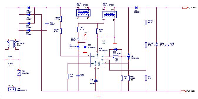
This article outlines a proposed solution for a 200 W power supply utilizing the FSFR2100 Fairchild Power Switch (FPS). The input voltage range is 90 to 265 VRMS, and it features six outputs. The 200 W power supply circuit based...
This circuit utilizes a relay to control a water pump, enabling automatic level control for a water reservoir or well. The shorter steel rod acts as the "water high" sensor, while the longer rod serves as the "water low"...
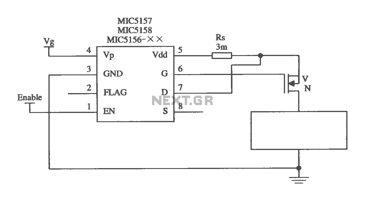
The MIC5156 is a device that incorporates a current limiting function, allowing it to handle high output currents. It can operate with or without a switching regulator circuit. The S terminal is left vacant, and a 16V Zener diode...
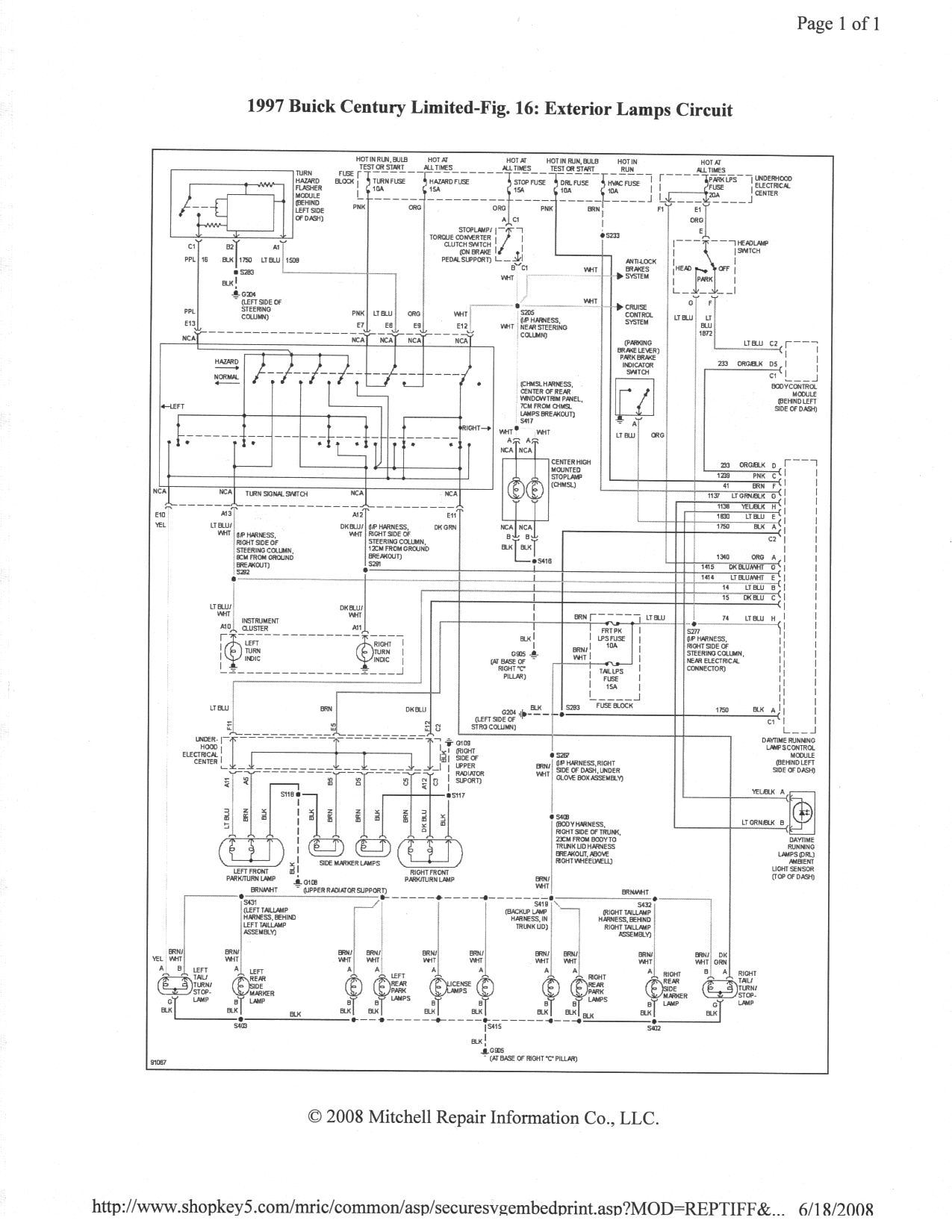
It is essential to ensure that none of the light bulbs on the vehicle are burnt out, particularly the turn signal lights, brake lights, and dashboard indicator lights. Malfunctions can occur when bulbs are burnt out. Utilizing the exterior...
A clock-controlled relay, also known as a time delay relay, allows for the automatic activation of a load, such as a water pump, at a predetermined time. This device utilizes a standard clock mechanism to trigger the circuit, enabling...
This device uses the second method, which requires about 100 times less parts, but adds motion detection to switch cameras. The usual way to detect motion is to store a complete video frame and then look for changes on...