
AM Radio built around LM555

The AM radio circuit utilizing the LM555 timer chip is a notable example of analog signal processing. The inductor used in the circuit, with its 300 turns of wire, plays a critical role in determining the resonant frequency of the LC tank circuit formed with the variable capacitor. This configuration allows for the selection of specific AM frequencies, enabling the user to tune into various radio stations. The choice of a cardboard tube for the inductor not only serves as a lightweight and cost-effective solution but also provides adequate insulation and structural integrity for the winding.
The implementation of the 555 timer in a pulse width modulation configuration is innovative, particularly in the context of radio signal demodulation. By utilizing the Threshold and Trigger pins for signal input, the circuit effectively avoids the limitations posed by the CV pin's low impedance. This design ensures that the incoming radio signals can modulate the PWM output effectively, allowing for the conversion of amplitude variations in the radio signal into corresponding variations in the duty cycle of the PWM signal.
The adjustment of the bias potentiometer is crucial for successful demodulation. By fine-tuning the bias, the circuit can selectively ignore certain portions of the incoming radio signal that do not contribute to the audio output, thereby enhancing sound quality and clarity. This selective clipping is particularly important in AM radio, where the signal can contain both positive and negative peaks that must be processed appropriately to avoid distortion.
Furthermore, the class-D power amplifier configuration of the LM555 ensures efficient amplification of the modulated signal, allowing for sufficient power to drive the speaker without significant energy loss. This efficiency is essential in portable or battery-operated radio designs, where power conservation is a priority.
In summary, the AM radio circuit featuring the LM555 timer chip exemplifies a clever integration of components to achieve effective AM signal reception and demodulation. The thoughtful design choices made in the configuration of the inductor, capacitor, and 555 timer contribute to a functional and efficient radio receiver capable of delivering clear audio output.AM radio built around 555 timer chip. The only active device (silicon, germanium, or otherwise) is the LM555. The tuning is accomplished with an inductor and a capacitor, and the LM555 acts as an AM demodulator and class-D power amplifier to drive the speaker. You may be wondering how all this is accomplished with a 555. Here`s how the circuit wor ks: The AM radio signal is tuned by inductor L, which is 300 turns of wire on a 1/2 inch diameter cardboard tube made out of a paper roll, along with the 100pF variable capacitor. One end of the parallel configuration of L and C connects to an antenna (surprisingly long!) and the other end connects to a ground wire which is tied to the AC outlet ground (old books tell you to ground it to a water pipe).
So far this is exactly like an AM crystal radio. The 555 timer is configured as a pulse width modulator in a non-traditional configuration. If I used the standard approach and connected the input to the CV pin, the low impedance of the pin would prevent the circuit from receiving any radio signals. I had to invert the circuit and tie both high impedance analog pins, Threshold and Trigger to the radio signal input.
This is the reason why the CMOS version of the 555 timer performs much better than the standard bipolar, which has higher input bias current. The pulse width modulator ramp is created by the 0. 01uF capacitor and the 10K bias potentiometer which are connected to the Discharge pin. The potentiometer wiper goes to the LC arrangement. With no radio signal coming in, the voltage on Threshold/Trigger ramps up until it hits the threshold, and then Discharge causes the voltage to ramp down again.
When a radio signal comes in, it gets superimposed on the ramp signal, causing the threshold and trigger comparators to trip early or late in a cycle. This variation causes the output duty cycle to vary, which we can hear as sound in the speaker. Demodulating the signal properly requires adjustment of the bias knob, so that part of the radio signal is clipped and ignored by either the threshold or trigger comparators.
This ensures that the negative halves of the radio wave don`t cancel out the positive halves . And of course, I can`t end the post without a gratuitous shot of the LM555 in circuit. 🔗 External reference
Related Circuits
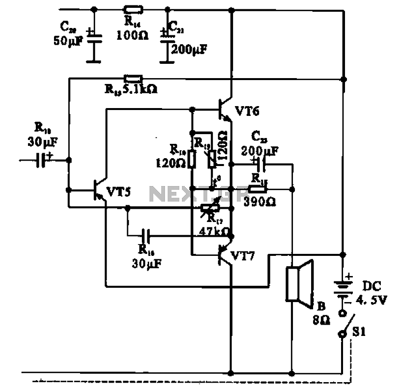
The transistor radio features a common output transformerless (OTL) power amplifier circuit. The VT5 component serves as the bias resistor for the driver stage. VT6 and VT7 form a complementary symmetry configuration, with VT6 being a germanium NPN transistor...
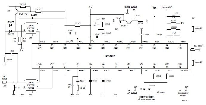
The integrated circuit (IC) is a multistandard vision and sound intermediate frequency (IF) phase-locked loop (PLL) demodulator that operates without the need for alignment. It supports multiple standards, including PAL, SECAM, and NTSC, and is capable of processing both...

The radio is a single-tuned set featuring dual 365 capacitors for tuning on both the antenna and detector sides of a single coil. The coil is designed with multiple taps, a concept that was initially unfamiliar but intriguing. The...

The circuit diagram and detailed explanation of a simple aircraft radio circuit are provided below. The simple aircraft radio circuit typically consists of several key components that work together to facilitate communication between the aircraft and ground stations or other...
A Tesla Coil can be understood as a high-power radio frequency transmitter with an inefficient antenna. The secondary coil functions as a significantly shortened quarter-wave antenna. The Tesla Coil is an electrical resonant transformer circuit that is designed to produce...
A regenerative radio operates by feeding back a small portion of the amplified output from the detector into the input. This feedback mechanism enhances sensitivity significantly beyond what a detector can achieve on its own. The simple regenerative radio...