
AM-Receiver for Aircraft comm (118.250MHz)
The described AM receiver operates at a center frequency of 118.250 MHz, which is commonly used for aviation communications. The receiver's architecture typically includes several key components: an RF front end, a mixer, a local oscillator, a demodulator, and an audio output stage.
The RF front end is designed to capture the incoming AM signal and filter out unwanted frequencies, allowing only the desired signal to pass through. This section may incorporate a bandpass filter centered around 118.250 MHz to enhance signal quality.
The manually tunable aspect of the receiver allows the user to adjust the frequency within a range of approximately 100 kHz, providing flexibility in tuning to different AM signals. This tuning can be achieved using a variable capacitor or an inductor in conjunction with the VCO, which generates a signal that can be mixed with the incoming RF signal.
The heart of the receiver, the Voltage Controlled Oscillator (VCO), plays a crucial role by generating a local oscillator signal that is mixed with the incoming AM signal. The VCO's frequency is controlled by a voltage input, allowing for precise tuning. The output of the VCO is fed into a mixer, where it combines with the incoming RF signal to produce an intermediate frequency (IF) signal. This IF signal is easier to process and demodulate.
The demodulation stage extracts the audio information from the AM signal, typically using envelope detection. This involves rectifying the IF signal and filtering it to recover the original audio waveform. The output from this stage is a low-level audio signal, typically in the range of 100-200 mV.
Due to the low output level, an audio amplifier is necessary to boost the signal for further processing or to drive speakers or headphones. While the specifics of the audio amplifier design are not covered, it is essential to ensure that the amplifier can handle the low-level input without introducing significant noise or distortion.
Overall, the described AM receiver is a straightforward yet effective design for receiving aviation communication signals, with key components working in unison to provide clear audio output from the AM modulated signals.The aircraft communication in Sweden is still Amplitud Modulated (AM). The local airport (Axamo) use the frequency 118.250 MHz. The reveiver I will explain is a tunable AM-receiver for this frequency. The receiver is instead manually tunable with some 100kHz around the 118MHz. The output from the receiver is a low level output (100-200mV) so you must connect it to some kind of amplifier. I will not explain how to build an audio-amplifier. The hart of the receiver is the Voltage Controlled Oscillator (VCO). 🔗 External reference
Related Circuits
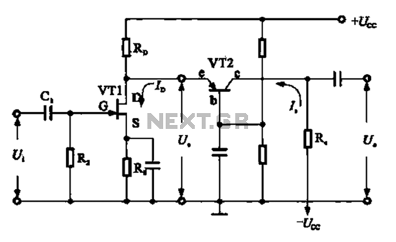
A combination of a common-source grounded base amplifier formed by cascaded amplifiers. The source is grounded, and a common base amplifier is combined into a cascaded amplifier. The graph below shows the low noise characteristics of the FET common-base...
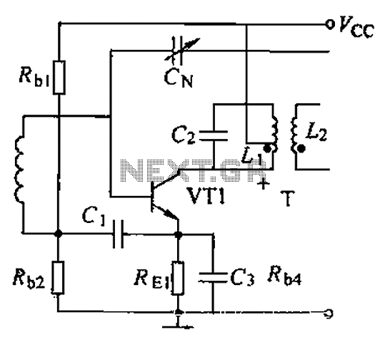
A common intermediate frequency amplifier circuit is presented, along with its components and parameters. The reference values for the components are as follows: 1) Transistors: VT1 to 3DG19, Vcc = 6V. 2) Resistance values: R1 = 50 kΩ, R2...

This document provides information about the Corsair and Commando Transmitters designed by Dave Martin of WNKR. It outlines the construction of each transmitter and includes examples created by others. The circuit diagram presented illustrates the initial two stages of...
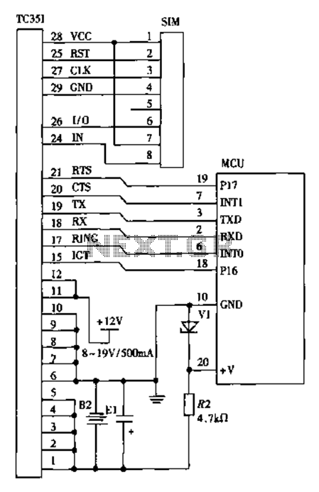
The design of a wireless data communication circuit is primarily intended for motor vehicles and fixed base station systems to facilitate close-range wireless data exchange. The circuit is based on the core chip nRF401 and its associated components. The...
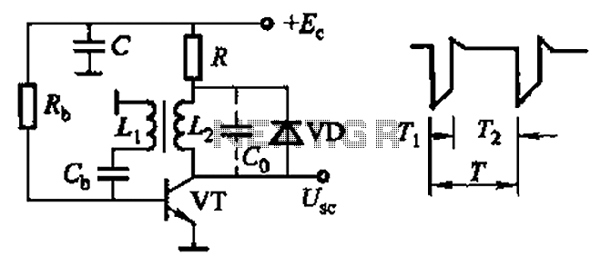
Common non-sinusoidal oscillator circuit, waveform and frequency formula - sawtooth oscillator - use blocking oscillator The sawtooth oscillator is a type of non-sinusoidal oscillator that generates a waveform characterized by a linear rise in voltage followed by a rapid drop....
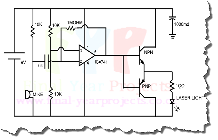
The objective of this project is to design a circuit for an electronic infrared communication system, develop innovative ideas for implementing this circuit, and study the circuitry along with various components such as DTMF generators, DTMF decoders, operational amplifiers,...